A non-refillable valve and its realization method

A non-repetitive, valve technology, used in lift valves, valve details, control valves, etc., can solve problems such as poor sealing performance and affect use, and achieve the effect of eliminating secondary filling, facilitating installation, and eliminating repeated filling.

Active Publication Date: 2016-04-13
ZHEJIANG KIN SHINE TECH
View PDF6 Cites 0 Cited by
  • Summary
  • Abstract
  • Description
  • Claims
  • Application Information

AI Technical Summary

Problems solved by technology

[0007] 3. The sealing performance is poor, which affects the use

Method used


Image

  • A non-refillable valve and its realization method
  • A non-refillable valve and its realization method
  • A non-refillable valve and its realization method

Examples


Embodiment 1

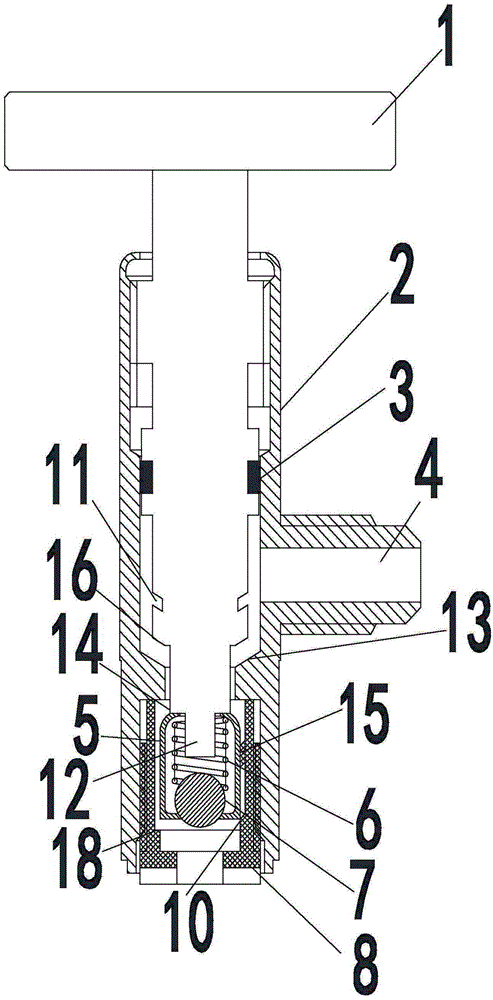
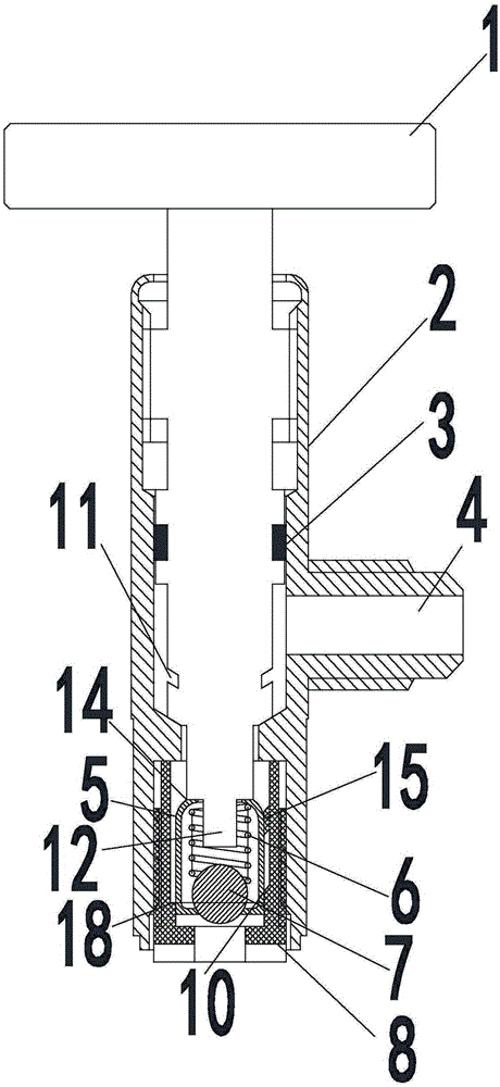
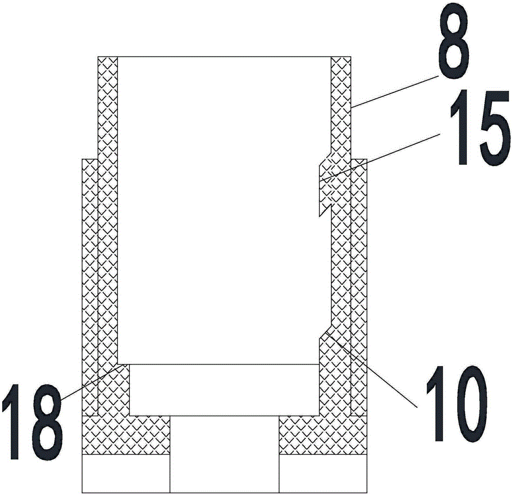
[0039] Such as Figure 1~4 As shown, a non-refillable valve includes a valve stem 1, a valve body 2, a sealing ring 3, an air inlet 4, a steel ball seat 5, a spring 6, a steel ball 7 and an inner sealing seat 8; wherein, the valve 1 The rod penetrates into the valve body 2, the air inlet 4 is set on one side of the valve body 2, and the sealing ring 3 is set inside the valve body 2, and the sealing ring 3 wraps the valve stem 1, specifically the middle and upper part, the purpose of the sealing ring 3 setting It is to prevent the gas from leaking out and escaping from the top; there is an installation part in the bottom of the valve body 1, and an inner sealing seat 8 is installed in the installation part, and a steel ball seat 5 is arranged in the inner sealing seat 8, and the gap between the inner sealing seat 8 and the steel ball seat is 5 The relationship: when not inflated, there is an inflation channel between the inner sealing seat 8 and the steel ball seat 5, when the ...

Embodiment 2

[0055] The difference between this embodiment and Embodiment 1 is that the spring 6 in this embodiment has a stiffness coefficient of 1.5 N / M, and an inclined groove 11 is provided on the valve stem 1 above the annular slope 16 with a width of 2 mm and a depth of 1 mm.


PUM


Abstract

The invention discloses a novel non-repeated filling valve which comprises a valve rod, a valve body, a sealing ring, an air inlet, a steel ball seat, a spring, a steel ball and an inner sealing seat. The valve rod penetrates into the valve body, the air inlet is formed in one side of the valve body, the sealing ring is arranged in the valve body, the valve rod is wrapped in the sealing ring, an installation part is arranged in the bottom of the valve body, the inner sealing seat is installed in the installation part, the steel ball seat is arranged in the inner sealing seat, the spring is arranged in the steel ball seat, the spring abuts against the steel ball, a top through hole and a bottom through hole are formed in the top and the bottom of the steel ball seat respectively, a part of the steel ball is exposed out of the bottom through hole, a protruding rod is arranged in the middle position of the bottom of the valve rod, penetrates through the top through hole and the spring and is located over the steel ball, and the periphery of the bottom of the valve rod abuts against the top of the steel ball seat. The invention further discloses an obtaining method of the novel non-repeated filling valve. The novel non-repeated filling valve has the advantages of being simple in structure, low in manufacturing cost, capable of completely eradicating secondary filling operation, good in sealing performance, suitable for application and popularization and the like.

Description

technical field [0001] The invention relates to liquid vaporization technology, in particular to a non-refilling valve and its realization method. Background technique [0002] Some steel cylinder countries strictly stipulate that its service life can only be used as a one-time use, and it is not allowed to be refilled and then sold on the market to avoid potential safety hazards. For this reason, non-refillable valves with various structures have appeared in the prior art. On steel cylinders to prevent refilling. [0003] Chinese Patent No. 200610053243.6 discloses a non-refillable valve for steel cylinders. Its structure includes a valve body, a valve nozzle, and components in the valve. There is a lower valve core and a supporting sleeve in the valve body cavity below the body partition, the bottom of the lower valve core is a sealing head, a medium circulation channel is provided on the lower valve core rod, and a temporary positioning ring is set on the periphery; the ...

Claims


Application Information

Patent Timeline
Patent Type & Authority Patents(China)
IPC IPC(8): F16K15/20F16K35/00
CPCF16K1/14F16K1/302F16K1/307
Inventor 杜加良许天其
Owner ZHEJIANG KIN SHINE TECH
Why Eureka
Try Eureka