
Absolute radiometric calibration method for satellite staring planar array CCD camera

A technology of absolute radiometric calibration and relative radiometric correction, which is applied in the direction of measuring devices and instruments, and can solve the problems of staring satellite area array CCD camera remote sensing applications starting late and unable to scientifically and objectively reflect the quantitative relationship between digital information and physical information.

Active Publication Date: 2014-10-08
CHINA CENT FOR RESOURCES SATELLITE DATA & APPL
View PDF4 Cites 19 Cited by
  • Summary
  • Abstract
  • Description
  • Claims
  • Application Information

AI Technical Summary

Problems solved by technology

At present, optical satellites operating in orbit mainly adopt the on-orbit absolute radiometric calibration method based on the radiometric correction site of Dunhuang remote sensing satellite (the center coordinates are 40.09°N, 94.39°E). , in order to image the Dunhuang remote sensing satellite radiometric correction site, it is necessary to carry out oblique lateral swing. In the case of squint angle measurement, there are serious problems in using the previous on-orbit absolute radiometric calibration method, which cannot reflect the digital information and physical information scientifically and objectively. Quantitative relationship between
At the same time, due to the late start of the remote sensing application of the staring satellite area array CCD camera, so far, there is no on-orbit absolute radiometric calibration method related to this aspect in the available literature.

Method used


Image

  • Absolute radiometric calibration method for satellite staring planar array CCD camera
  • Absolute radiometric calibration method for satellite staring planar array CCD camera
  • Absolute radiometric calibration method for satellite staring planar array CCD camera

Examples


Embodiment Construction

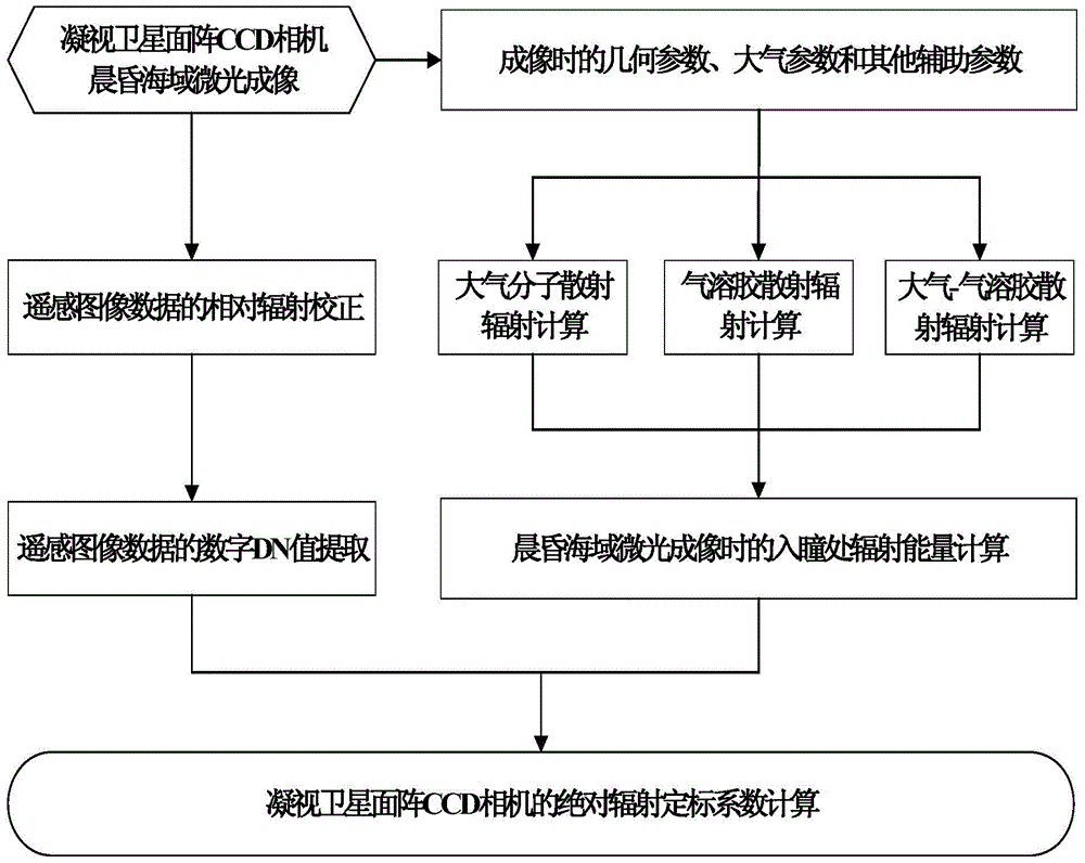
[0048] (1) Establishment of the absolute radiometric calibration model: based on the basic idea of ​​absolute radiometric calibration and considering the linear working area of ​​the camera design, the digital DN value information and Stare at the linear quantitative relationship of the radiation energy information at the entrance pupil of the satellite area array CCD camera;

[0049] DN R (i, j) = f G [L(i,j)]

[0050] ①

[0051] =Gain×L(i,j)+Bias

[0052] In the formula: i, j are the detector positions of the area array CCD camera (i∈[1,K], j∈[1,L]);

[0053] DN R (i, j) is the digital DN value of detector (i, j) after relative radiation correction;

[0054] L(i,j) is the radiation energy radiation value at the entrance pupil of the probe (i,j);

[0055] Gain and Bias are the absolute radiation calibration coefficients of the area array CCD camera.

[0056] (2) Establishment of the radiant energy model at the e...


PUM


Abstract

The invention relates to an absolute radiometric calibration method for a satellite staring planar array CCD camera. The absolute radiometric calibration method comprises the steps of firstly establishing a linear quantitative relationship between digital DN value information after relative radiometric calibration for remote sensing image data of the satellite staring planar array CCD camera and radiation energy information at entrance pupil of the satellite staring planar array CCD camera, and a radiation energy model at the entrance pupil of the satellite staring planar array CCD camera in sea imaging; then calculating to obtain radiation energy L at the entrance pupil of the satellite staring planar array CCD camera in low light level imaging of the sea area at morning or nightfall and acquire a sample average value of all probing digital DN values of the satellite staring planar array CCD camera after the relative radiometric calibration to be used as an average digital DN value DNR of the satellite staring planar array CCD camera probing units; and finally performing linear fitting on the above L and DNR and calculating to obtain an absolute radiometric calibration coefficient. The absolute radiometric calibration method overcomes the technical problem of no absolute radiometric calibration method for in-orbit operation of the satellite staring planar array CCD camera.

Description

technical field [0001] The invention relates to an absolute radiation calibration method for a staring satellite area array CCD camera, in particular to an absolute radiation calibration method for a geosynchronous orbit satellite area array camera. Background technique [0002] Staring satellites can continuously observe the phenomena in the field of view in real time and at fixed points, and can also directly customize continuous observations according to user needs. Its flexible and continuous observation methods can not only qualitatively obtain binary information about the "target area of ​​interest". Digital information can also quantitatively obtain the physical energy radiation information of the target, and the quantitative conversion process from the binary digital information of the remote sensing image data to the physical energy radiation information is called absolute radiation calibration. At present, optical satellites operating in orbit mainly adopt the on-o...

Claims


Application Information

Patent Timeline
IPC IPC(8): G01C25/00
CPCG01C25/00
Inventor 王爱春傅俏燕闵祥军陆书宁潘志强李晓进韩启金张学文刘李李照洲
Owner CHINA CENT FOR RESOURCES SATELLITE DATA & APPL
Learn More