Timer circuit used for COT control mode switching adjustor

A timer circuit and switching regulator technology, applied in the field of electronics, can solve the problems of EMI dispersion, insufficient precision and linearity, etc.

Inactive Publication Date: 2014-10-08
UNIV OF ELECTRONICS SCI & TECH OF CHINA
View PDF5 Cites 5 Cited by
  • Summary
  • Abstract
  • Description
  • Claims
  • Application Information

AI Technical Summary

Problems solved by technology

[0004] The purpose of the present invention is to solve the problem that the switching frequency is affected by the input voltage, output voltage and load current in the above-mentioned COT control mode, causing EMI dispersion, and the accuracy and linearity are not high enough. tor timer circuit

Method used


Image

  • Timer circuit used for COT control mode switching adjustor
  • Timer circuit used for COT control mode switching adjustor
  • Timer circuit used for COT control mode switching adjustor

Examples


Embodiment Construction

[0012] The specific embodiment of the present invention is described below in conjunction with accompanying drawing

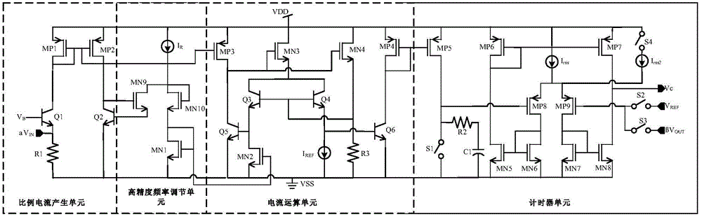
[0013] like figure 2 As shown, it is a schematic diagram of the circuit structure of the switching regulator timing module of the COT control mode of the present invention, and the circuit includes a proportional current generation unit, a high-precision frequency adjustment unit, a current operation unit and a counter unit connected in sequence; wherein, the proportional current The generating unit is composed of PMOS transistor MP1, transistors Q1 and Q2, and resistor R1; among them, the source of MP1 is connected to the power supply VDD, its gate and drain are interconnected, its gate is connected to the gate of MP2, and its drain is connected to Q1. The collector; the base of Q1 is connected to VB (VB is a fixed bias voltage to ensure the normal operation of Q1), and its emitter is grounded to VSS through R1; the source of MP2 is connected to the power sup...


PUM


Abstract

The invention relates to the field of electronic technologies, in particular to a high-precision timer circuit used for a COT control mode DC-DC converter. The timer circuit is adjustable in on -time. The circuit comprises a proportion current generating unit, a high-precision frequency adjusting unit, a current arithmetic unit and a counter unit in a sequential connection mode. The timer circuit has the advantages that the on-time can be inversely proportional to input voltage and be directly proportional to output voltage; switching frequency is determined by resistance and capacitance and kept constant, and changes, caused by the technology and temperature excursion of the resistance, of a resistance value are offset; the constant switching frequency overcomes the defects that switching conversion of a traditional COT control circuit changes along with the output voltage, and EMI is not concentrated; in different application environments, the COT is adjustable.

Description

technical field [0001] The invention relates to the field of electronic technology, in particular to a high-precision timer circuit with adjustable conduction time applied to a COT control mode DC-DC converter. Background technique [0002] The hysteretic mode has been widely used because of its quick response to load dynamics, simple structure, and no need for loop compensation. However, the switching frequency of the hysteretic mode switching power supply is determined by the input voltage, output voltage, equivalent output resistance ESR, inductance, output capacitance, etc. As long as any of these factors change, the switching frequency will be affected, which will have many adverse effects on the system. The constant on-time control mode (COT) is a control circuit derived from the hysteretic control mode. The on-time of each cycle is kept constant, and the input signal is adjusted by adjusting the off-time. Compared with the fixed off-time control mode, the switching f...

Claims


Application Information

Patent Timeline
Patent Type & Authority Applications(China)
IPC IPC(8): H02M3/00
Inventor 周泽坤张瑜石跃赵倬毅王卓张波
Owner UNIV OF ELECTRONICS SCI & TECH OF CHINA
Why Eureka
Try Eureka