Dual-sliding mode control based speed regulating system and method for direct torque of permanent magnet synchronous motor main axis

A permanent magnet synchronous and speed regulating system technology, applied in the direction of control system, direct torque control, general control strategy, etc., can solve problems such as noise and chattering, and the system is difficult to control accurately, and achieve the solution of flux linkage and torque ripple Large, fast dynamic response, fast dynamic response effect

Inactive Publication Date: 2019-03-01
JIANGSU UNIVERSITY OF TECHNOLOGY
View PDF4 Cites 3 Cited by
  • Summary
  • Abstract
  • Description
  • Claims
  • Application Information

AI Technical Summary

Problems solved by technology

[0006] In order to solve the large flux linkage and torque pulsation caused by the traditional direct torque control strategy of the existing permanent magnet synchronous electric spindle, the system is difficult to accurately control at low speeds, and the noise and chattering caused by flux linkage and torque pulsation etc., the present invention provides a permanent magnet synchronous electric spindle direct torque speed regulation system and method based on double sliding mode control, which is used to reduce the fluctuation of flux linkage and torque, improve the dynamic and static performance of the system, and ensure the CNC machining accuracy

Method used


Image

  • Dual-sliding mode control based speed regulating system and method for direct torque of permanent magnet synchronous motor main axis
  • Dual-sliding mode control based speed regulating system and method for direct torque of permanent magnet synchronous motor main axis
  • Dual-sliding mode control based speed regulating system and method for direct torque of permanent magnet synchronous motor main axis

Examples


Embodiment Construction

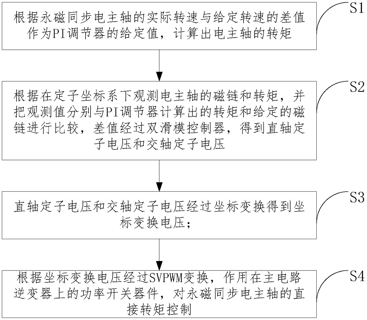
[0049] In order to make the purpose, technical solutions and advantages of the embodiments of the present invention clearer, the technical solutions in the embodiments of the present invention will be clearly and completely described below in conjunction with the drawings in the embodiments of the present invention. Obviously, the described embodiments It is a part of embodiments of the present invention, but not all embodiments. Based on the embodiments of the present invention, all other embodiments obtained by persons of ordinary skill in the art without creative efforts fall within the protection scope of the present invention.

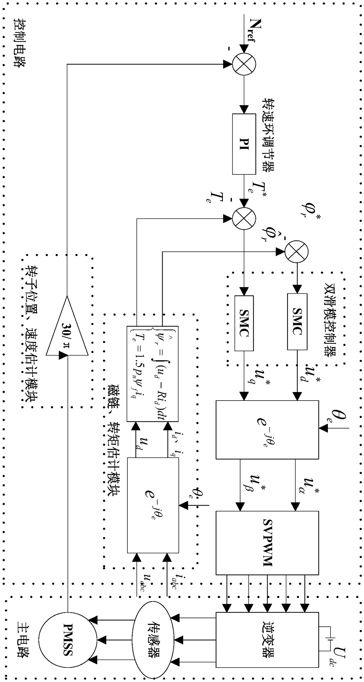
[0050] combine figure 1 , a permanent magnet synchronous electric spindle direct torque speed regulation system based on double sliding mode control, including a main circuit, a control circuit, and a signal detection circuit.

[0051] The main circuit includes an inverter and a permanent magnet synchronous spindle (PMSS).

[0052] The control c...


PUM


Abstract

The invention provides a dual-sliding mode control based speed regulating system and method for direct torque of a permanent magnet synchronous motor main axis. The speed regulating method comprises the following steps: calculating the torque of the motor main axis according to the difference value of the actual rotating speed of the permanent magnet synchronous motor main axis and the given rotating speed of the permanent magnet synchronous motor main axis as a given value of a PI regulator; detecting the stator current and voltage of the motor main axis by using a sensor, observing the fluxlinkage and torque of the motor main axis under a stator coordinate system, comparing observed values with the torque calculated by the PI regulator and the given flux linkage respectively, obtainingdirect axis voltage and quadrature axis stator voltage by using the difference value through a dual-sliding mode controller, acting on a power switch device on a main circuit inverter through coordinate conversion and SVPWM conversion, and thus realizing direct torque control of the permanent magnet synchronous motor main axis. The speed regulating system is simple in structure, easy to realize and good in robustness, and has the advantages of high torque response speed and small tracking error, so that the stability of the system and the machining precision of parts are improved.

Description

technical field [0001] The invention belongs to the technical field of numerical control machining, and in particular relates to a permanent magnet synchronous electric spindle direct torque speed regulation system and method based on double sliding mode control. Background technique [0002] As one of the core components of high-precision CNC machine tools, permanent magnet synchronous electric spindle has the advantages of simple structure, high power factor, good low-speed performance, and low loss. It is widely used in occasions requiring high precision and high reliability. Direct torque control is a comprehensive control of flux linkage and torque centered on torque. Unlike vector control, direct torque control does not require decoupling. It adopts the concept of stator flux orientation and space vector, and through the stator voltage Carry out integration, directly observe the flux linkage and torque of the motorized spindle in the stator coordinate system, and compa...

Claims


Application Information

Patent Timeline
IPC IPC(8): H02P23/00H02P23/30H02P25/022
CPCH02P23/0009H02P25/022H02P2207/05H02P23/30
Inventor 单文桃李永俊张健荣
Owner JIANGSU UNIVERSITY OF TECHNOLOGY
Why Eureka
Try Eureka