
Pump unit driven by an electric motor

A technology of pump components and motors, which is applied in the direction of engine components, pump components, engine functions, etc., can solve the problems of manufacturability cost and assembly investment of complex structures, and achieve the reduction of acoustic reflection, improvement of acoustic decoupling, and reduction of assembly investment small effect

Active Publication Date: 2014-10-08
CONTINENTAL AUTOMOTIVE TECH GMBH
View PDF9 Cites 3 Cited by
  • Summary
  • Abstract
  • Description
  • Claims
  • Application Information

AI Technical Summary

Problems solved by technology

Furthermore, components such as diaphragm pumps have a relatively complex structure and there is a need for optimized manufacturability and reduced cost and assembly effort

Method used


Image

  • Pump unit driven by an electric motor
  • Pump unit driven by an electric motor
  • Pump unit driven by an electric motor

Examples


Embodiment Construction

[0045] Since the basic mode of operation of a pump assembly of the same type and of a pneumatic brake booster that can be connected to such a pump assembly is sufficiently known, it will not be described in detail hereinafter, as long as this is not considered to be necessary for the description of the present invention. Words matter.

[0046] figure 1

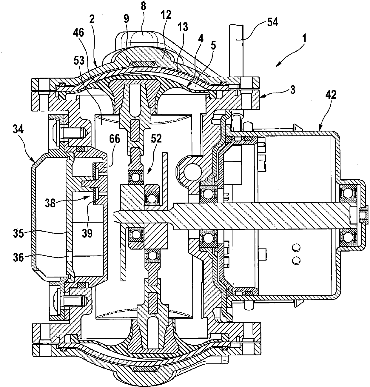
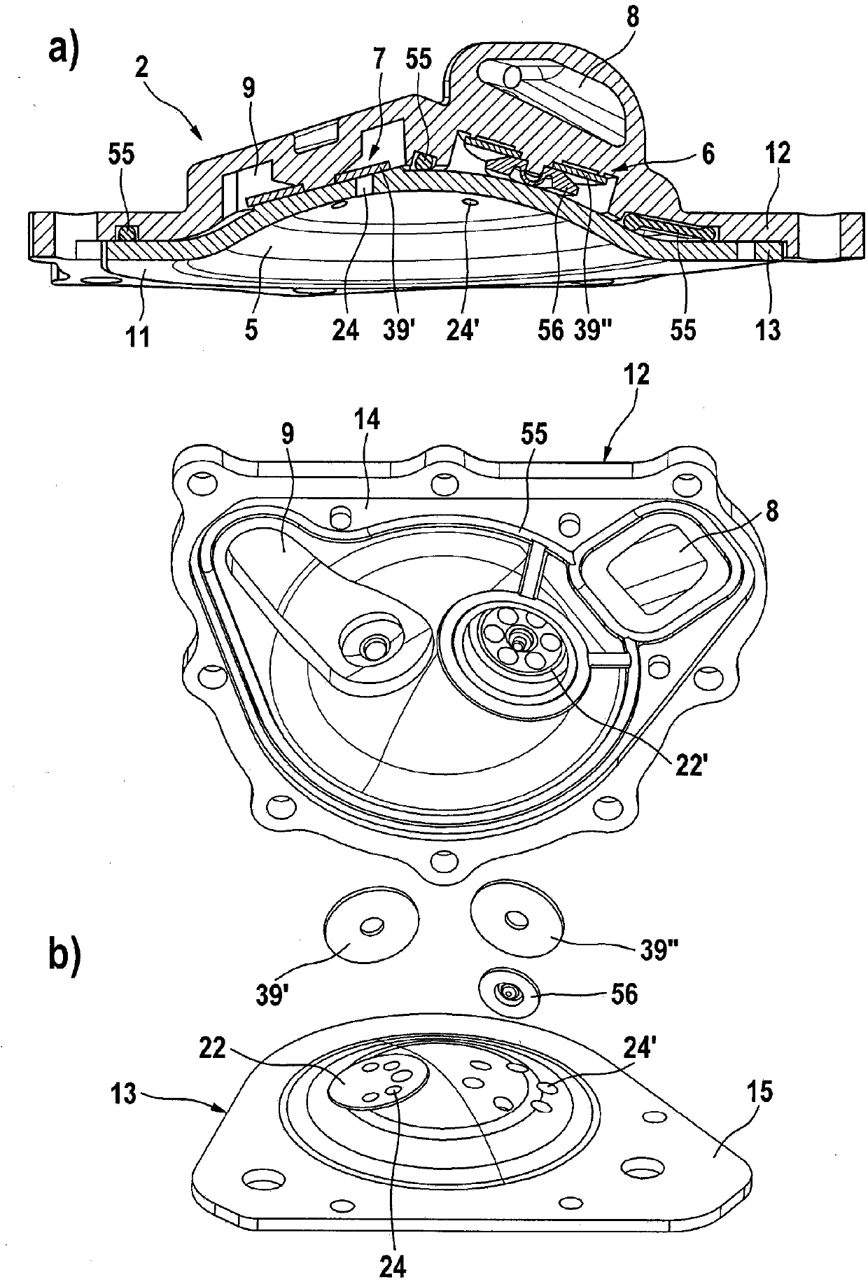
[0047] figure 1 A known pump assembly 1 is shown. The pump assembly is designed as a double-diaphragm pump with two mutually opposite displacement elements 4 . The displacement elements 4 each have an elastic diaphragm element 46 which is respectively stretched airtight between the pump housing 3 and the working chamber cover 2 and thus delimits the working chamber 5 . An inlet valve 6 and an outlet valve 7 , not shown, as well as an inlet channel 8 and an outlet channel 9 , which are pneumatically connected to the valves, are assigned to each working chamber. In this case, inlet channel 8 is connected pneumatically to co...


PUM


Abstract

The invention relates to a pump unit (1) that can be driven by an electric motor, in particular for providing vacuum for a pneumatic brake booster, comprising a pump housing (3) that can be closed by a working-chamber cover (2) and at least one elastic displacement element (4), wherein a working chamber (5) is bounded between the displacement element (4) and the working-chamber cover (2) and wherein inlet valves (6) and outlet valves (7) and inlet channels (8) and outlet channels (9) associated with the valves are associated with the working chamber. According to the invention, in order to reduce noise emissions, means for reducing a contact surface between the working-chamber cover (2) and the pump housing (3) are provided.

Description

technical field [0001] The invention relates to an electric motor-drivable pump assembly according to the preamble of claim 1 . Background technique [0002] Brake boosters are used to boost braking force in hydraulic braking systems, of which pneumatic or vacuum brake boosters are a very popular, reliable and cost-effective solution. [0003] An underpressure is required to provide the vacuum for the pneumatic brake booster, the interior of which is divided into at least one vacuum chamber and one working chamber. In many cases, the required underpressure can be ensured by the connection of the vacuum chamber to the suction line of the self-priming internal combustion engine. In the case of diesel, turbocharged or electric drives and increased braking force requirements due to, for example, higher vehicle weight, the vacuum supply can only be insufficiently or even not provided by the vehicle drive. In order to reliably ensure a sufficient vacuum supply, a separate vacuum...

Claims


Application Information

Patent Timeline
Patent Type & Authority Applications(China)
IPC IPC(8): F04B9/04F04B39/00F04B45/04F04B45/047
CPCF04B9/042F04B39/0055F04B45/047F04B43/025F04B39/0044F04B43/04F04B53/102F04B9/045F04B45/04F04B45/043F04B53/10F04B53/001F04B53/16F05B2260/96F05B2260/40F05B2210/12
Inventor S·克雷布斯J·巴彻尔H·克雷L·米利希奇M·于尔根宁M·尼埃彭伯格J·冈萨雷斯K·塞茨H-M·科佩尔F·佩佐尔德R·菲灵格尔S·伊姆霍夫T·欧芬内尔P·维贝尔M·吕费尔
Owner CONTINENTAL AUTOMOTIVE TECH GMBH
Learn More