
Refrigerating cycle device

A refrigeration cycle and refrigerant technology, used in refrigerators, refrigeration components, refrigeration and liquefaction, etc., can solve the problems of wide setting range of refrigerant encapsulation amount and insufficient refrigerant, reduce the diameter of pipes and suppress the reduction of efficiency Effect

Active Publication Date: 2014-10-08
HITACHI JOHNSON CONTROLS AIR CONDITIONING INC
View PDF8 Cites 15 Cited by
  • Summary
  • Abstract
  • Description
  • Claims
  • Application Information

AI Technical Summary

Problems solved by technology

However, there is no description about the diameter of the connecting pipe of the refrigeration cycle device using refrigerant R32, or the description about the length of the connecting pipe, and the setting range of the amount of refrigerant enclosed is wide.
Therefore, in the case of the amount at the lower limit of the setting range of the enclosed refrigerant quantity described in Patent Document 2, no additional refrigerant is enclosed during construction of the refrigeration cycle device, and only the refrigerant enclosed at the time of shipment is used. In the case of the maximum connection piping length (chargeless maximum piping length), there is a problem that the refrigerant may be insufficient

Method used


Image

  • Refrigerating cycle device
  • Refrigerating cycle device
  • Refrigerating cycle device

Examples


Embodiment 1

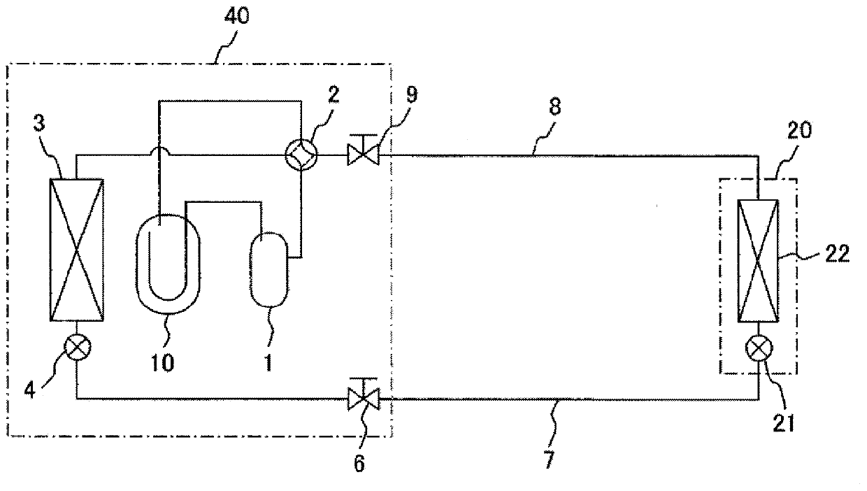
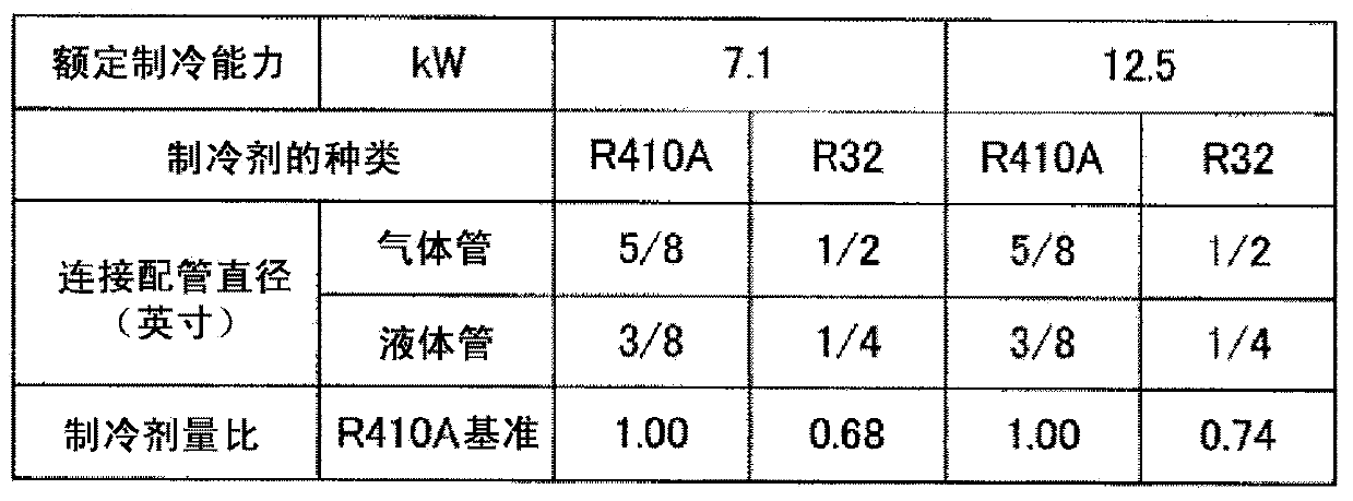
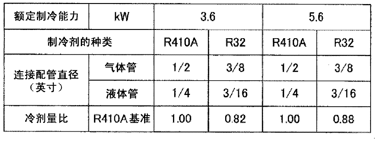
[0037] pass Figure 1 ~ Figure 3 Embodiment 1 of the refrigeration cycle apparatus of the present invention will be described. figure 1 It is a circulation system diagram for explaining Embodiment 1 of the refrigeration cycle apparatus of the present invention, figure 2 It is a diagram for explaining the connection pipe diameter and the refrigerant quantity ratio in a refrigeration cycle device (rated refrigeration capacity: 7.1kW, 12.5kW) using refrigerants R410A and R32 having equal COPs, image 3 It is a diagram for explaining connection pipe diameters and refrigerant quantity ratios in a refrigeration cycle apparatus (rated refrigeration capacities of 3.6 kW and 5.6 kW) using refrigerants R410A and R32 having equal COPs.

[0038] figure 1 An air conditioner as a refrigeration cycle device is shown, and an outdoor unit 40 and an indoor unit 20 are connected by a liquid-side connecting pipe 7 and a gas-side connecting pipe 8 . In the outdoor unit 40, reference numeral 1 ...

Embodiment 2

[0064] pass Figure 4 , Figure 5 Embodiment 2 of the refrigeration cycle apparatus of the present invention will be described. Figure 4 It is a graph showing the refrigerant quantity ratio (refrigerant quantity ratio equal to COP) with respect to the R410A standard of the rated refrigeration capacity in a refrigeration cycle device using refrigerant R32, Figure 5 It is a diagram for explaining the COP ratio based on R410A when the amount of refrigerant is equalized in a refrigeration cycle apparatus using refrigerants R410A and R32, and also shows the diameter of connecting pipes.

[0065] In the first embodiment above, the outer diameter of the connecting pipes 7 and 8 of the refrigeration cycle device using the refrigerant R32 is one order smaller than that of the connecting pipes 7 and 8 of the refrigeration cycle device using the refrigerant R410A. ,pass Figure 4 The amount of refrigerant (upper limit and lower limit) enclosed in the refrigeration cycle apparatus us...


PUM


Abstract

The purpose of the present invention is to inhibit a reduction in efficiency and reduce the pipe diameter of connection pipes while a refrigerant having a low global warming potential (GWP) is used. A refrigerating cycle device is composed of a compressor (1), a heat source equipment-side heat exchanger (3), a first expansion device (4), a liquid-side connection pipe (7), a second expansion device (21), a usage-side heat exchange (22), and a gas-side connection pipe (8), the preceding being connected in the stated order. Also, the refrigerant used in the refrigerating cycle is R32, the outside diameter of the liquid-side connection pipe and the gas-side connection pipe is "(D0-1) / 8 inches" (wherein "D0 / 8 inches" is the outside diameter of the connection pipe when refrigerant R410A is used), the range of D0 is "2<=D0<=4" in the liquid connection pipe, and the range of D0 is "3<=D0<=8" in the gas connection pipe.

Description

technical field [0001] The present invention relates to a refrigeration cycle device such as an air conditioner and a refrigerator utilizing a refrigeration cycle, and particularly to a refrigeration cycle device using R32 (difluoromethane) as a refrigerant used in the refrigeration cycle. Background technique [0002] Currently, in refrigerating and air-conditioning equipment such as air conditioners and refrigerators, more and more devices use refrigerant R410A as the refrigerant sealed in the refrigeration cycle. Refrigerant R410A can improve the efficiency of refrigerating and air-conditioning equipment, and reduce the amount of carbon dioxide produced during power generation by reducing power consumption thereby. In addition, suppression of refrigerant discharge by means of countermeasures against refrigerant leakage and the like is also achieved, thereby contributing to the prevention of global warming. [0003] However, since refrigerant R410A is a refrigerant with a...

Claims


Application Information

Patent Timeline
Patent Type & Authority Applications(China)
IPC IPC(8): F25B41/00F25B1/00
CPCF25B2500/01F25B41/003F25B13/00F25B41/00F25B2400/12F25B41/40
Inventor 坪江宏明横关敦彦塚田福治中山进
Owner HITACHI JOHNSON CONTROLS AIR CONDITIONING INC
Learn More