Efficient photocatalytic air purifier

An air purifier and photocatalysis technology, applied in chemical instruments and methods, dispersed particle separation, combined devices, etc., can solve problems such as low utilization efficiency of ultraviolet rays

Inactive Publication Date: 2014-10-15
王汉培
View PDF0 Cites 2 Cited by
  • Summary
  • Abstract
  • Description
  • Claims
  • Application Information

AI Technical Summary

Problems solved by technology

[0005] The problem to be solved by the present invention is to provide a new structure of photocatalytic air purifier, overcome the problem of low ultraviolet utilization efficiency of existing photocatalytic air purifiers, improve the reaction rate of photocatalysis, and achieve the purpose of providing purification ability

Method used


Image

  • Efficient photocatalytic air purifier
  • Efficient photocatalytic air purifier
  • Efficient photocatalytic air purifier

Examples


Embodiment Construction

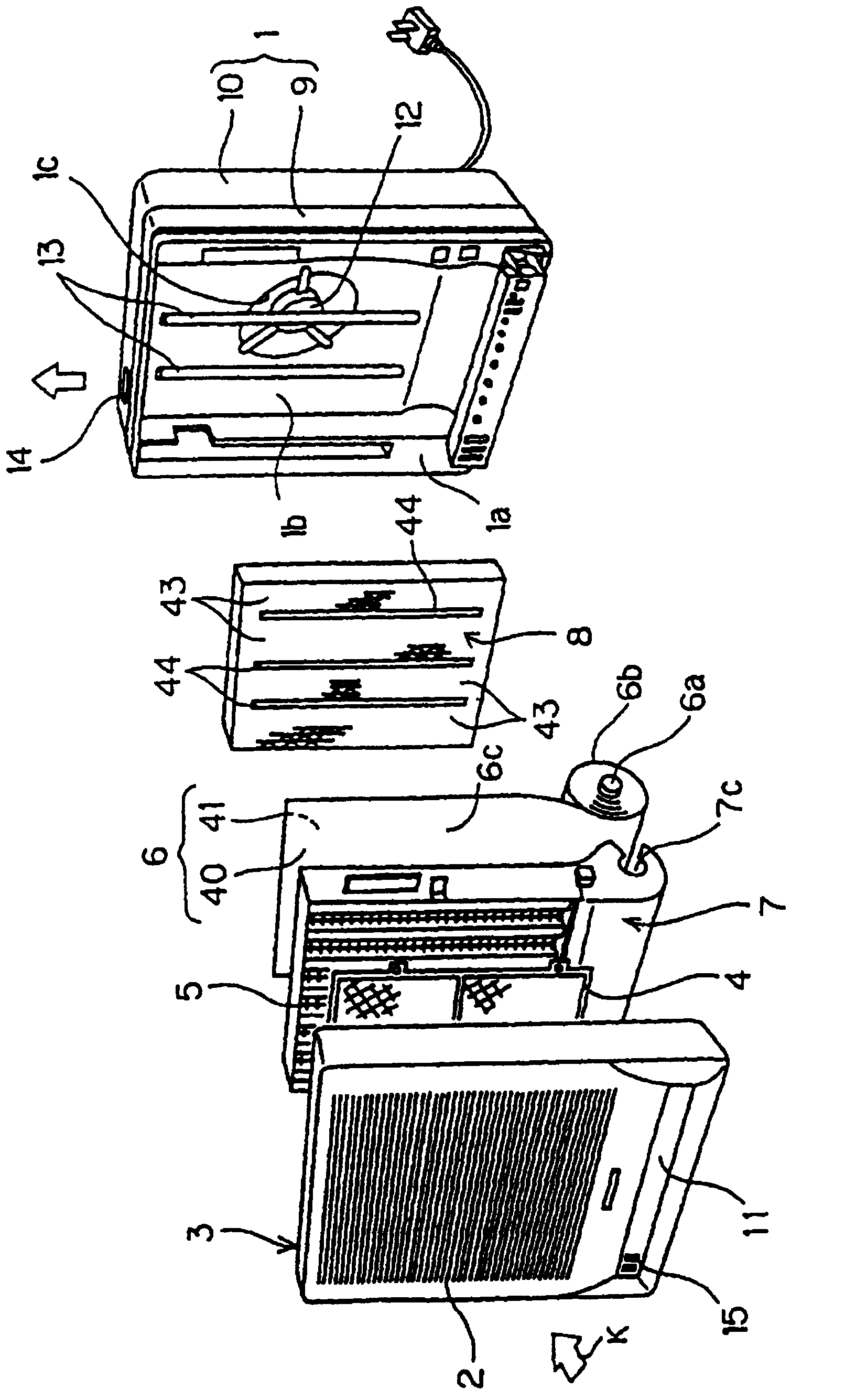
[0016] figure 1 Shown is an exploded perspective view of an air cleaner including an ionization unit in one embodiment of the present invention. Referring to this figure, in the air cleaner of the present invention, the frontmost part of the air cleaner main body 1 is covered with a front panel 3 provided with an intake grill 2 . Air is sucked into the air cleaner subject through the suction grille 2 .

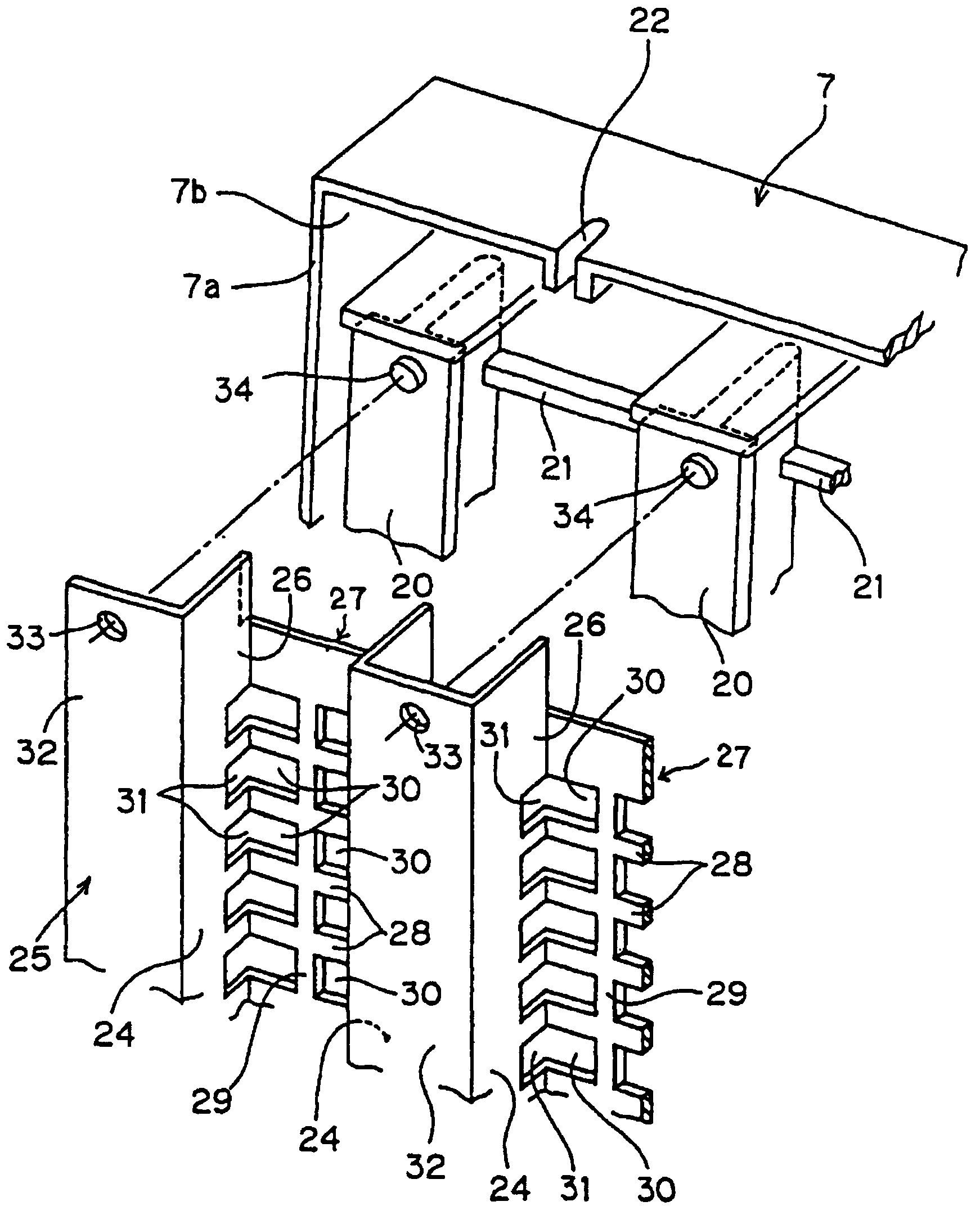
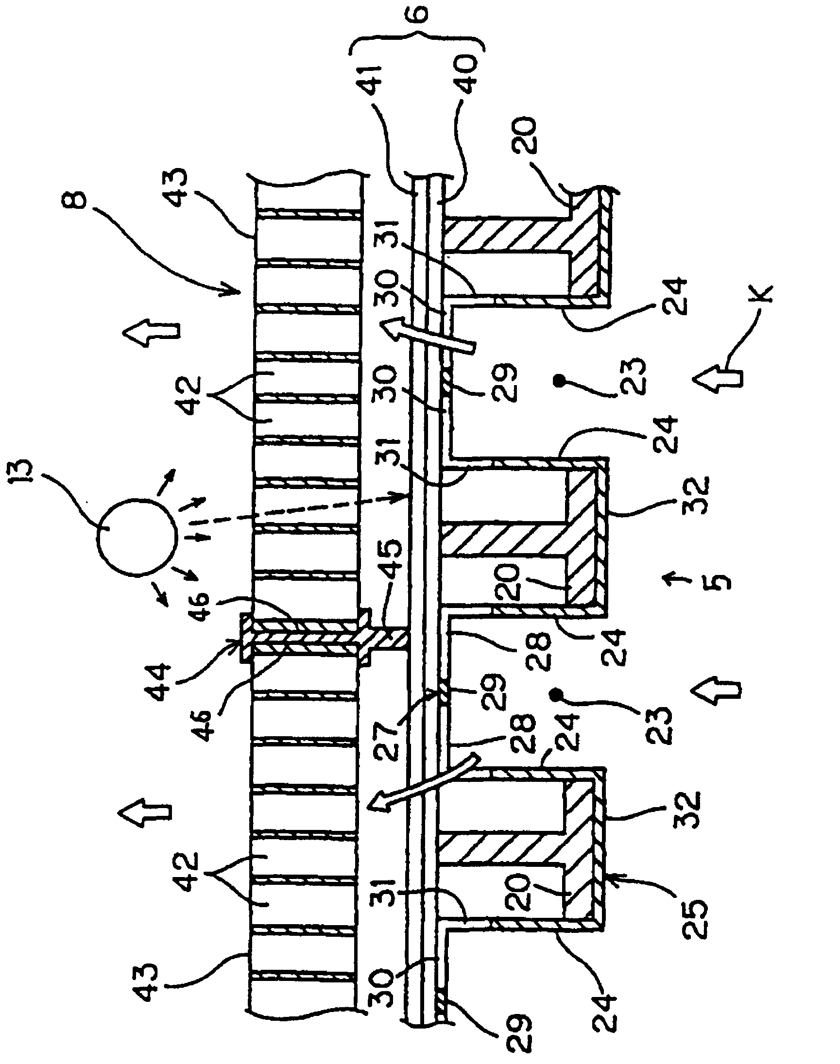
[0017] A concave portion 1b is formed on the front surface 1a of the air cleaner main body 1 . In the recess 1b, a coarse filter 4 for removing larger particles of garbage and dust, a filter housing 7 with a mechanism for removing dust, and a photocatalytic reaction device 8 for purifying pollutants can be arranged. In the filter case 7, the ionization part 5 is attached to the front part, and the roll filter 6 including the electrostatic filter 40 as a dust collection part is attached to the back side. The photocatalytic reaction device 8 constitutes a honeycomb photocatal...


PUM


Abstract

The invention relates to an efficient photocatalytic air purifier. A plate-like photocatalyst part and a honeycomb photocatalyst part are arranged in a particular sequence and structure, so that the light from the light source lamp penetrates through the vents of the honeycomb photocatalyst, and irradiates on the plate-like photocatalyst part to the effective use light source and increase the conversion efficiency of photocatalyst, thereby enhancing the purification ability of the air purifier.

Description

technical field [0001] The invention relates to an air purification device, in particular to an air purification device which uses a photocatalytic method to decompose pollutants in the air. Background technique [0002] The structure of the air cleaner of the conventional electric dust collection method is to ionize the dust in the circulating airflow at the ionization part, and then adsorb the ionized dust to the dust collecting part provided on the downstream side of the ionization part in the flow direction of the airflow. The above-mentioned ionization part includes a plurality of long ionization lines and each pair of opposing electrode plates respectively sandwiching these ionization lines and arranged oppositely. As the dust collection part installed on the downstream side of the ionization part, there is an electrode plate-shaped electrostatic filter in which cathode plates and anode plates are alternately stacked. Although this electrical dust collection method ca...

Claims


Application Information

Patent Timeline
Patent Type & Authority Applications(China)
IPC IPC(8): B01D53/86B01D50/00
Inventor 王汉培
Owner 王汉培
Why Eureka
Try Eureka