A vehicle integrated electro-hydraulic braking system

A brake system, integrated electro-hydraulic technology, applied in the direction of brakes, vehicle components, brake transmissions, etc., can solve the problems of reduced reliability, high cost, complex structure, etc., and achieve adjustable brake pedal feel and pressure regulation The effect of high precision and small pressure fluctuation

Active Publication Date: 2016-08-31
南京经纬达汽车科技有限公司
View PDF3 Cites 0 Cited by
  • Summary
  • Abstract
  • Description
  • Claims
  • Application Information

AI Technical Summary

Problems solved by technology

However, for the traditional hydraulic braking system used in passenger cars and other light vehicles, which account for about 80% of the total number of automobiles, its structure has seriously restricted the electronicization and intelligence of automobiles and the braking energy of new energy vehicles. Use of Recycling Technology
[0003] The traditional hydraulic braking system has three obvious deficiencies: one is that active braking cannot be implemented conveniently (the so-called "active braking" refers to the fact that all or part of the wheels can still be controlled when the driver does not step on the brake pedal. braking), so it is difficult to meet the active braking requirements of chassis active control systems such as adaptive cruise control and electronic stability programs; second, as long as the driver steps on the brake pedal, the friction brake will start to work and consume energy, which seriously hinders the The braking energy recovery of new energy vehicles such as electric vehicles and hybrid vehicles is realized; the third is that the traditional hydraulic braking system is vacuum assisted, but there is no vacuum source on new energy vehicles, and a separate vacuum source is required to meet the functional requirements of the system. lead to complex structure and high cost
The more functions are added to the brake system, the more complex the structure of the brake system becomes, which also increases its cost and reduces its reliability

Method used


Image

  • A vehicle integrated electro-hydraulic braking system
  • A vehicle integrated electro-hydraulic braking system

Examples


Embodiment Construction

[0042] The present invention will be further described below in conjunction with accompanying drawing.

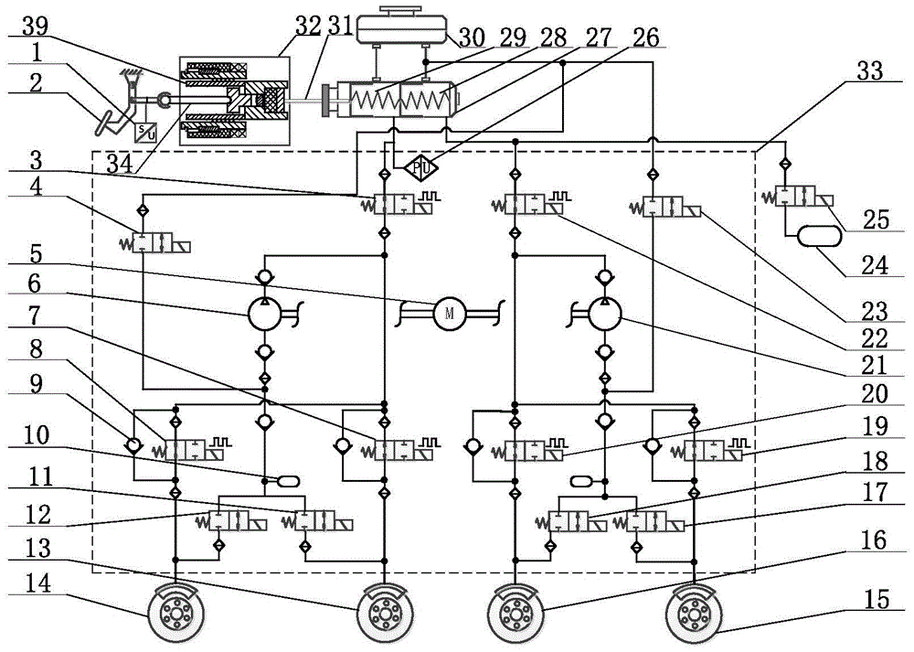
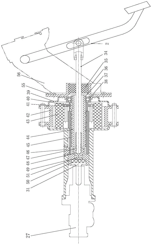
[0043] The vehicle integrated electro-hydraulic brake system of the present invention includes an electric brake booster device 32, a brake pedal 2, a pedal stroke simulator 24, a hydraulic control unit 33 and sensor components.

[0044] Described brake pedal 2 links to each other with pedal bracket 56 through support pin, and pedal bracket 56 is fixedly connected with the rear end face of firewall 55 on the automobile. Brake pedal 2 links to each other with the input end of brake push rod 34 through spherical seat, to prevent the impact of brake pedal 2 push rod vertical direction movement on brake push rod 34; The piston push rods 31 of the dual-chamber brake master cylinders are connected to each other. During the braking process, the brake pedal 2 is depressed by manpower, so that the brake push rod 34 moves forward, and then the piston push rod 31 of the brake master ...


PUM


Abstract

The invention relates to a vehicle integrated electro-hydraulic braking system, which is composed of a brake pedal, a brake master cylinder and its electric brake booster, a pedal stroke simulator, a hydraulic control unit, a brake wheel cylinder and a brake pipeline composition. The present invention proposes that the electric brake booster and manpower independently or superimposedly act on the plunger rod of the master brake cylinder piston, thereby pushing the brake master cylinder piston to perform braking. The vehicle integrated electro-hydraulic braking system of the present invention can work in power-assisted braking mode, active braking mode, regenerative auxiliary braking mode, and manual backup braking mode according to different braking requirements. The brake master cylinder is connected to the hydraulic control unit through two normally open isolation valves and connected to the pedal stroke simulator through a commonly used simulator valve. When the vehicle needs to implement regenerative braking, the brake master cylinder is connected to the The hydraulic control unit is isolated, and the brake master cylinder is communicated with the pedal travel simulator through the simulator valve, and the brake pedal feel is provided by the pedal travel simulator.

Description

technical field [0001] The invention is a vehicle integrated electro-hydraulic braking system, specifically, a novel braking system integrating the functions of electric braking power assist braking, active braking, regenerative braking and human backup braking. Background technique [0002] With the continuous advancement of science and technology and the improvement of people's living standards, the safety, energy saving and environmental protection performance of automobiles are getting more and more attention, and the automobile braking system is one of the main research directions of automobile active safety. However, for the traditional hydraulic braking system used in passenger cars and other light vehicles, which account for about 80% of the total number of automobiles, its structure has seriously restricted the electronicization and intelligence of automobiles and the braking energy of new energy vehicles. Use of recycling technology. [0003] The traditional hydra...

Claims


Application Information

Patent Timeline
Patent Type & Authority Patents(China)
IPC IPC(8): B60T13/74B60T13/66
Inventor 邓伟文丁能根
Owner 南京经纬达汽车科技有限公司
Why Eureka
Try Eureka