
Wing of ornithopter

A wing and airfoil technology, applied in the field of flapping wing, can solve the problems of not being suitable for micro-aircraft, low efficiency, complex structure, etc., and achieve the effect of simple structure, small resistance, large lift and thrust

Active Publication Date: 2014-10-15
徐州博创建设发展集团有限公司
View PDF8 Cites 0 Cited by
  • Summary
  • Abstract
  • Description
  • Claims
  • Application Information

AI Technical Summary

Problems solved by technology

[0002] The traditional flapping wing is an integral structure, and the resistance is relatively large when flapping up, and the efficiency is not high; the Chinese patent application with the publication number CN1608945A discloses a flapping wing of an aircraft with a double-layer oblique truss structure. Opening and closing to improve flapping efficiency has certain effects, but the structure is complex and not suitable for micro air vehicles

Method used


Image

  • Wing of ornithopter
  • Wing of ornithopter
  • Wing of ornithopter

Examples


Embodiment Construction

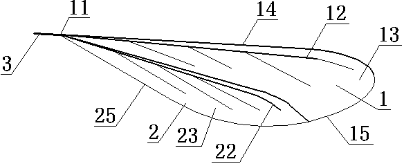
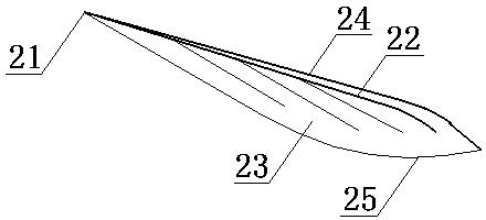
[0010] now attached Figure 1~4 The present invention is described in detail: a flapping wing, consisting of a main wing 1, an aileron 2 and a rocker 3. The main wing 1 includes the main wing root 11 , the main wing frame 12 and the main wing skin 13 , and the aileron 2 includes the aileron root 21 , the aileron frame 22 and the aileron skin 23 . Both the main wing frame 12 and the aileron frame 22 are in the shape of dendrites, the main wing leading edge 14 is relatively thick, the position where the main wing trailing edge 15 connects with the aileron leading edge 24 protrudes downward, and the aileron leading edge 24 protrudes upward, and the aileron rear edge 24 protrudes upwards. Edge 25 is thinner. The aileron root 21 is more elastic than other parts of the airfoil. The planar shape of the whole wing is similar to leaves; the leading edge of the whole wing is the main wing leading edge 14 which is relatively straight, and the leading edge at the tip of the wing has som...


PUM


Abstract

The invention discloses a wing of an ornithopter and belongs to the technical field of aircraft. The wing of the ornithopter is composed of a main wing, an auxiliary wing and a rocker. The main wing comprises a main wing root, a main wing framework and a main wing skin, the auxiliary wing comprises an auxiliary wing root, an auxiliary wing framework and an auxiliary wing skin. Both the main wing framework and the auxiliary wing framework are branch-shaped, the front edge of the main wing is thicker, one part of the rear edge of the main wing protrudes downward, the front edge of the auxiliary wing protrudes upwardly, and the rear edge of the auxiliary wing is thinner. The wing root of the auxiliary wing is more elastic than the other parts of the wing. The wing plane is leaf-shaped. The rear edge of the main wing is arranged on the front edge of the auxiliary wing in a lapping mode, and the downward protruded part near the rear edge of the main wing is hooked with the upward protruded part of the front edge of the auxiliary wing. The auxiliary wing root is connected below the main wing root, and the main wing root is connected with one end of the rocker. The wing is simple in structure, is capable of generating large lift force and thrust, and is high in efficiency.

Description

technical field [0001] A flapping-wing wing piece belongs to the technical field of aircraft, and in particular relates to a flapping-wing wing piece. Background technique [0002] The traditional flapping wing is a single piece of structure, and the resistance is relatively large when flapping upwards, and the efficiency is not high; the Chinese patent application with the publication number CN1608945A discloses a flapping wing of an aircraft with a double-layer oblique truss structure, which utilizes the movable feather plate Opening and closing to improve flapping efficiency has a certain effect, but the structure is complex and not suitable for micro air vehicles. Contents of the invention [0003] The purpose of the present invention is to overcome the above-mentioned deficiency of traditional flapping-wing wing, invent a kind of simple-structured flapping-wing wing of higher efficiency. [0004] A flapping wing consists of a main wing, an aileron and a rocker. The ...

Claims


Application Information

Patent Timeline
Patent Type & Authority Applications(China)
IPC IPC(8): B64C33/02
Inventor 王志成
Owner 徐州博创建设发展集团有限公司
Learn More