Collapsing manufacture method with improved axial evenness for core rods of optical fiber preforms

A technology of optical fiber preform and manufacturing method, which is applied in the field of optical fiber manufacturing, and can solve the problems of no improvement in the axial uniformity of the core layer parameters of the prefabricated rod, and achieve the reduction of optical fiber preparation costs, the increase of the length of the core rod, and the improvement of production efficiency Effect

Inactive Publication Date: 2014-10-15
YANGTZE OPTICAL FIBRE & CABLE CO LTD
View PDF3 Cites 9 Cited by
  • Summary
  • Abstract
  • Description
  • Claims
  • Application Information

AI Technical Summary

Problems solved by technology

[0005] There are not many reports on modifying the parameters of the preform mandrel by the melting and shrinking process. The US patent US 7637125 proposes to use a graphite heating furnace for

Method used


Image

  • Collapsing manufacture method with improved axial evenness for core rods of optical fiber preforms
  • Collapsing manufacture method with improved axial evenness for core rods of optical fiber preforms
  • Collapsing manufacture method with improved axial evenness for core rods of optical fiber preforms

Examples


Embodiment 1

[0025] Example 1: For the detection of the axial distribution of the core diameter of the doped quartz liner, the deposited SiO has an outer diameter of 45mm, a wall thickness of 15mm, and a length of 2.5m. 2 Liner with doped SiO deposited on the inner wall 2 (with GeO 2 etc.), place it on the preform (mandrel) shrinkage equipment;

[0026] Use the graphite heating furnace jacket to provide the heat source, set the power of the heating element, the furnace body moves at a speed of 40~45mm / min, the rotation speed of the quartz liner is 24rad / min, and the surface temperature of the liner is about 2000~2100°C;

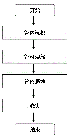
[0027] When the temperature of the heating element rises to 2000°C, the first melting and shrinkage begins, and the mixed gas (O 2 and C 2 f 6 ), the gas flow is accurately controlled by the flow controller, and the gas pressure at the gas outlet end of the liner is controlled at the same time, and it is stabilized within a certain range to ensure a uniform and contro...

Embodiment 2

[0030] Embodiment 2: take the SiO that the outer diameter is 45mm, the wall thickness is 15mm, and the length is 2.5m. 2 Liner, inner wall core deposited doped SiO 2 (with GeO 2 etc.), the quartz liner and the deposition process parameters are the same as in the first embodiment, which is placed on the same shrinkage equipment as in the first embodiment;

[0031]Use the graphite heating furnace jacket to provide the heat source, set the power of the heating element, the furnace jacket moves at a speed of 40~45mm / min, the rotation speed of the quartz liner is 24rad / min, and the surface temperature of the liner is about 2000~2100℃;

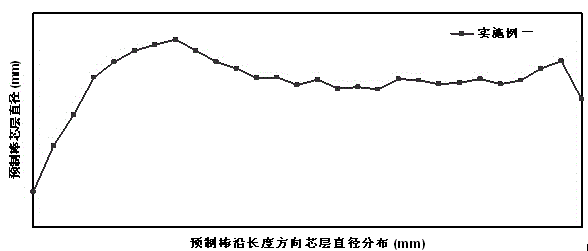
[0032] According to the core layer diameter distribution of the preform produced by the same process parameters of the same equipment measured in advance (same as embodiment one, image 3 ), set each trip C 2 f 6 The curve of the relationship between the dosage and the position of the graphite heating furnace. The position of the graphite heatin...

Embodiment 3

[0035] Embodiment three: get outside diameter and be 45mm, wall thickness is 15mm, and length is the deposited SiO of 2.5m Liner, inner wall core layer deposits doped SiO 2 (with GeO 2 etc.), the quartz liner and the deposition process parameters are the same as in the first embodiment, which is placed on the same shrinkage equipment as in the first embodiment;

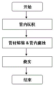
[0036] A graphite heating furnace is used to provide the heat source, the furnace moves at a speed of 40-45mm / min, the rotation speed of the quartz liner is 24rad / min, and the surface temperature of the liner is about 2000-2100oC. In this example, the method of melting and shrinking first and then corroding will be used to sinter the prefabricated core rod.

[0037] When the temperature of the heating element rises to 2000°C, the first melting and shrinkage begins, and O2 gas is introduced from one end of the pipe, and the gas flow is precisely controlled by the flow controller, while the gas pressure at the gas outl...


PUM


Abstract

The invention relates to a collapsing manufacture method with improved axial evenness for core rods of optical fiber preforms. The method comprises the following steps: mounting a quartz-doped liner tube on a collapsing lathe, rotating the quartz-doped liner tube, moving a heating furnace jacket from one end of the liner tube to the other end of the liner tube in the axial direction of the liner tube, collapsing the liner tube gradually to realize solid burning. During the collapsing process, the two ends of the liner tube are sealed, and O2 gas is led into the liner tube. The method is characterized in that the axial distribution condition of the sandwich layer diameter of the liner tube after deposition is confirmed before collapsing, and an F-contained corrosive gas is led into the liner tube during the collapsing process of the liner tube to conduct different axial corrosion on the inner wall of the liner tube, or O2 gas and the F-contained corrosive gas are led into the liner tube simultaneously after collapsing and before solid burning to conduct different axial corrosion on the inner wall of the liner tube. The method has the advantages that the effect that different areas in the liner tube are corroded differently is realized by adjusting the flow rate of corrosive mixed gas, and fixed point corrosion is realized, so that the diameter evenness of the core rods of the optical fiber preforms can be improved remarkably. Therefore, optical fiber preparation cost can be reduced; the production efficiency can be improved.

Description

technical field [0001] The invention relates to a shrinkage manufacturing method of an optical fiber prefabricated core rod, which uses a preformed rod shrinkage process to adjust the axial uniformity of the core layer of the optical fiber preformed rod, and belongs to the technical field of optical fiber manufacturing. Background technique [0002] Currently known manufacturing processes for optical fiber preforms typically include in-tube vapor deposition processes, such as MCVD (modified chemical vapor deposition) improved chemical vapor deposition and PCVD (plasma chemical vapor deposition) plasma-induced chemical vapor deposition, as well as out-of-tube Vapor deposition process, such as OVD (outside vapor deposition) external vapor deposition process and VAD (vapor axial deposition) external axial deposition process. [0003] For the optical fiber preform core rod prepared by in-tube deposition methods such as PCVD or MCVD, during the waveguide structure deposition proc...

Claims


Application Information

Patent Timeline
IPC IPC(8): C03B37/014
Inventor 黄利伟龙胜亚朱继红周红燕王润涵周游陈刚
Owner YANGTZE OPTICAL FIBRE & CABLE CO LTD
Why Eureka
Try Eureka