Method for operating internal combustion engine

An internal combustion engine and combustion chamber technology, applied in the direction of internal combustion piston engine, combustion engine, engine starting, etc., can solve the problems of complex manufacturing of pressure reducing valves, and achieve the effect of preventing smooth operation.

Inactive Publication Date: 2014-10-15
ANDREAS STIHL AG & CO KG
View PDF8 Cites 0 Cited by
  • Summary
  • Abstract
  • Description
  • Claims
  • Application Information

AI Technical Summary

Problems solved by technology

However, it has been shown that the combustion pressure (which is present due to the late ignition moment) is not always reliably sufficient to close the pressure relief valve in the known pressure relief valves.
In order to ensure that the pressure relief valve is closed reliably by the combustion pressure at idle, narrow tolerances at the pressure relief valve must be maintained, which results in a more complicated manufacture of the pressure relief valve

Method used


Image

  • Method for operating internal combustion engine
  • Method for operating internal combustion engine
  • Method for operating internal combustion engine

Examples


Embodiment Construction

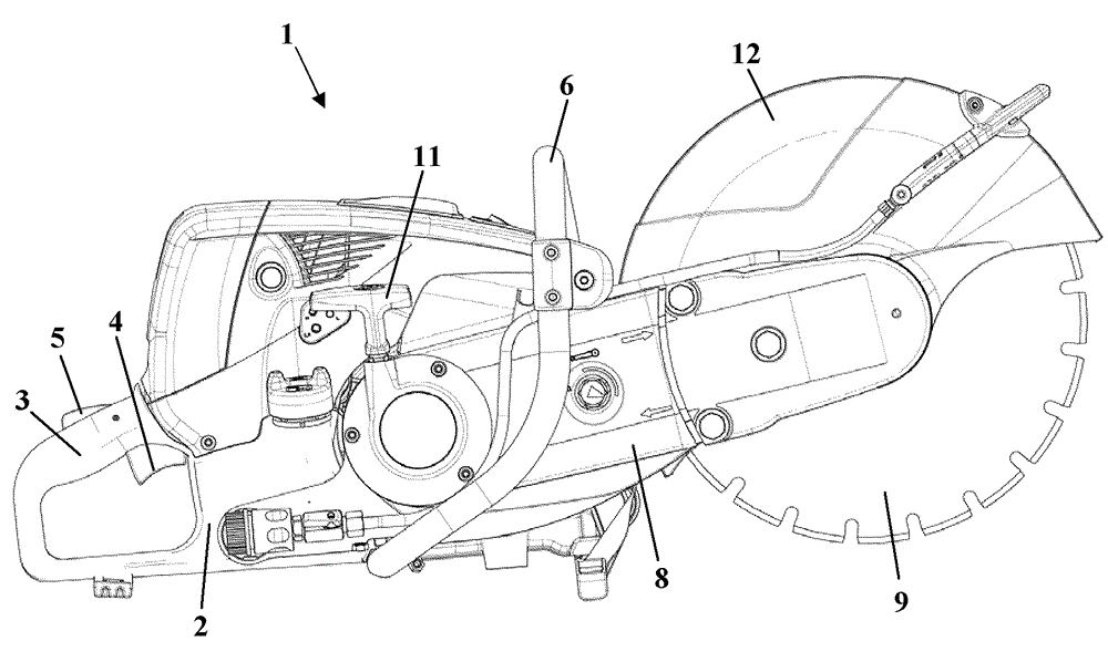
[0024] figure 1 A cutting machine 1 is shown as an example for a portable hand-held power tool. The method for operating an internal combustion engine, which will be explained in more detail below, can also be used in internal combustion engines for other fields of application, in particular in other work implements such as power saws, free cutters, blowers, jet implements, harvesting implements, mowers, etc. In internal combustion engines such as lawn mowers. The cutting machine 1 has a housing 2 to which two handles for guiding the cutting machine 1 during operation, namely a rear handle 3 and a handle 6 , are fastened. A throttle lever 4 and a throttle lever lock 5 are pivotably mounted on the rear handle 3 . On the side of the housing 2 facing away from the rear handle 3 a cantilever 8 projects forward, at its free end a cutting disc 9 is rotatably mounted. The cutting disk 9 is covered over a part of its circumference by a protective cover 12 . Arranged in the housing...


PUM


Abstract

The invention relates to a method for operating an internal combustion engine. The internal combustion engine includes a cylinder and a piston journalled to reciprocate therein. The cylinder and piston conjointly delimit a combustion chamber into which a spark plug projects. Ignition of the spark plug occurs at an ignition time point controlled by a control unit. The ignition time point is controlled in an idle speed range according to an idle control having a most advanced ignition time point. The engine has a decompression valve which, when open, connects the combustion chamber to a pressure relief space. The valve is open during engine start and closes when pressure in the combustion chamber exceeds a closing pressure. To close the valve, the ignition occurs in the idle speed range for an engine cycle departing from the idle control at a closing ignition time point lying approximately 5 DEG crankshaft angle ahead of the most advanced ignition time point.

Description

technical field [0001] The invention relates to a method for operating an internal combustion engine of the type specified in the preamble of claim 1 . Background technique [0002] An internal combustion engine is known from DE 195 04 105 A1, which has a pressure reduction device. When the cable starter is actuated, this known decompression device is automatically triggered and the decompression valve is opened here. The pressure relief valve is closed due to the combustion pressure generated in the cylinder during combustion. [0003] The ignition of the internal combustion engine is usually controlled by a control device. In the idling speed range, the ignition takes place at a relatively late ignition time. During idling, it should thus be ensured that the rotational speed does not rise too much, so that a constant idling rotational speed and only minor rotational speed fluctuations are obtained during idling. However, it has been found that with known pressure relie...

Claims


Application Information

Patent Timeline
Patent Type & Authority Applications(China)
IPC IPC(8): F02D17/04F02P5/04
CPCY02T10/46F02D41/1497F02N19/004F02P5/1508F02P5/1506F02D35/023F02D2400/06F02D13/0276F02P5/145F02P5/1512F02N3/02Y02T10/40F02P5/153
Inventor M.拉芬贝格C.克拉特
Owner ANDREAS STIHL AG & CO KG
Why Eureka
Try Eureka