
Lubricating structure used for clutch device of motorcycle

A clutch device and lubricating structure technology, applied in friction clutches, clutches, mechanical drive clutches, etc., can solve the problems of inability to control the supply of lubricant, lack of reliability of the structure, and inability to handle the situation where lubricant is supplied

Inactive Publication Date: 2014-10-15
SUZUKI MOTOR CORP
View PDF10 Cites 3 Cited by
  • Summary
  • Abstract
  • Description
  • Claims
  • Application Information

AI Technical Summary

Problems solved by technology

[0008] However, in the lubricating structure of the conventional clutch device, the cost of the nozzle part and the press-fitting process are required, which is the main cause of the cost increase
[0009] Further, the structure disclosed in Patent Document 1 lacks reliability because the supply amount of lubricant cannot be controlled
More specifically, it may not be able to handle situations where excess lubricant is being supplied, requiring some kind of throttling structure

Method used


Image

  • Lubricating structure used for clutch device of motorcycle
  • Lubricating structure used for clutch device of motorcycle
  • Lubricating structure used for clutch device of motorcycle

Examples


Embodiment Construction

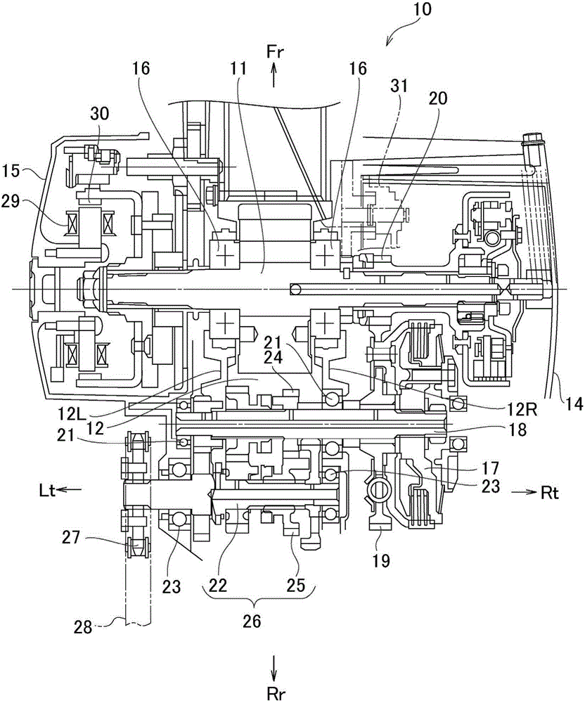
[0026] Preferred embodiments of a lubrication structure for a clutch device for a motorcycle according to the present invention will be described below based on the drawings.

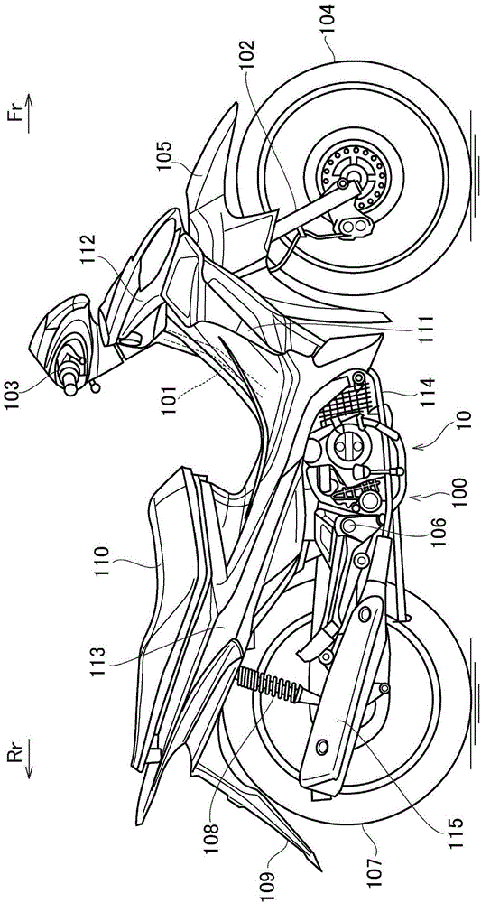
[0027] figure 1 It is a side view of the motorcycle 100 according to an application example of the present invention. First, use figure 1 The overall configuration of the motorcycle 100 will be described. Note that in the following descriptions include figure 1 In the drawings, the arrow Fr indicates the front side of the vehicle, the arrow Rr indicates the rear side of the vehicle, the arrow Rt indicates the right side of the vehicle, and the arrow Lt indicates the left side of the vehicle, as necessary.

[0028] In motorcycle 100 , the vehicle body frame is formed of a steel or aluminum alloy body frame, and is configured by assembling various components to the body frame. As a configuration example of the body frame, the body frame may be, for example, a so-called bent beam type, and although det...


PUM


Abstract

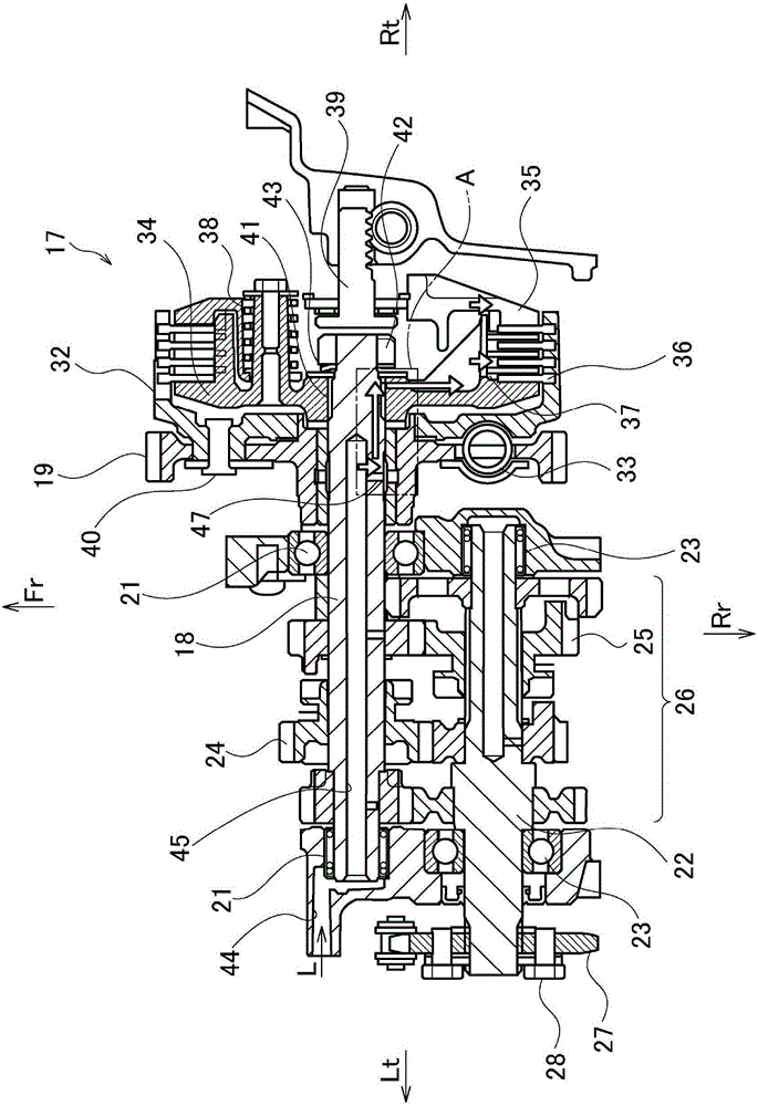
The present invention provides a lubricating structure used for a clutch device of a motorcycle, wherein a plurality of driving friction plates and driven friction plates are alternately arranged between a clutch casing and a sleeve hub, the clutch casing is driven by a crank shaft and rotates around a counter shaft, the sleeve hub is linked with the counter shaft and rotates together with the counter shaft. A spline is formed to enable the counter shaft and the sleeve hub to be connected with each other, the spline serves as a lubricating oil channel, and through the lubricating oil channel, proper throttling is performed for the lubricating oil supplied to peripheral regions of the driving friction plates and the driven friction plates.

Description

[0001] Cross-references to related applications [0002] This application claims priority to Japanese Patent No. 2013-083216 filed on April 11, 2013, and the entire contents of the prior application are hereby incorporated by reference. technical field [0003] The present invention typically relates to a lubricating structure for a clutch device, particularly a multi-plate wet clutch device used in a motorcycle engine. Background technique [0004] In the multi-plate wet clutch, lubricating oil (lubricant) is supplied to the overlapped portion of the friction plates in order to reduce heat generation and wear of the friction plates (clutch driver plate and clutch follower plate). In this case, the excessive supply of oil deteriorates the clutch disengagement characteristic during shifting, so a lubricating structure is adopted in which the supply amount of oil is throttled to adjust the amount to a moderate supply amount. [0005] Specifically, mainly in motorcycles of the...

Claims


Application Information

Patent Timeline
Patent Type & Authority Applications(China)
IPC IPC(8): F16D13/74
Inventor 长尾诚今成修一西尾祐二
Owner SUZUKI MOTOR CORP
Learn More