Multi-mode operation evaporative cooling water supply device and its use method
A multi-mode operation, evaporative refrigeration technology, applied in application, heating mode, household appliances, etc., can solve the problems of energy waste, single operation mode, and inability to solve the unit’s winter antifreeze, etc., to achieve convenient use, reasonable structure, and wide application range Effect
- Summary
- Abstract
- Description
- Claims
- Application Information
AI Technical Summary
Problems solved by technology
Method used
Image
Examples
Embodiment 1
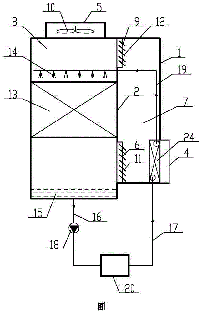
[0026] Embodiment 1: as attached figure 1 As shown, the multi-mode operation evaporative refrigeration water supply device includes an evaporative refrigeration device 2, and the evaporative refrigeration device 2 includes an evaporative refrigeration packing 13, a spray device 14, a circulating water tank 15, a circulating water pump 18, an exhaust duct 8, and a refrigeration device The lower air inlet 6 has an air chamber 7 on the outside of the evaporative refrigeration device 2 corresponding to the lower air inlet 6 of the refrigeration device. There is a first air inlet port 4 at the bottom of the air chamber 7. The evaporative refrigeration device 2 is provided with a ventilation chamber 7 With the upper air inlet 9 of the refrigeration device of the exhaust duct 8, the first air inlet port 4 communicates with the lower air inlet 6 of the refrigeration device through the air chamber 7, and the first air inlet port 4 communicates with the upper air inlet 9 of the refrigera...
Embodiment 2
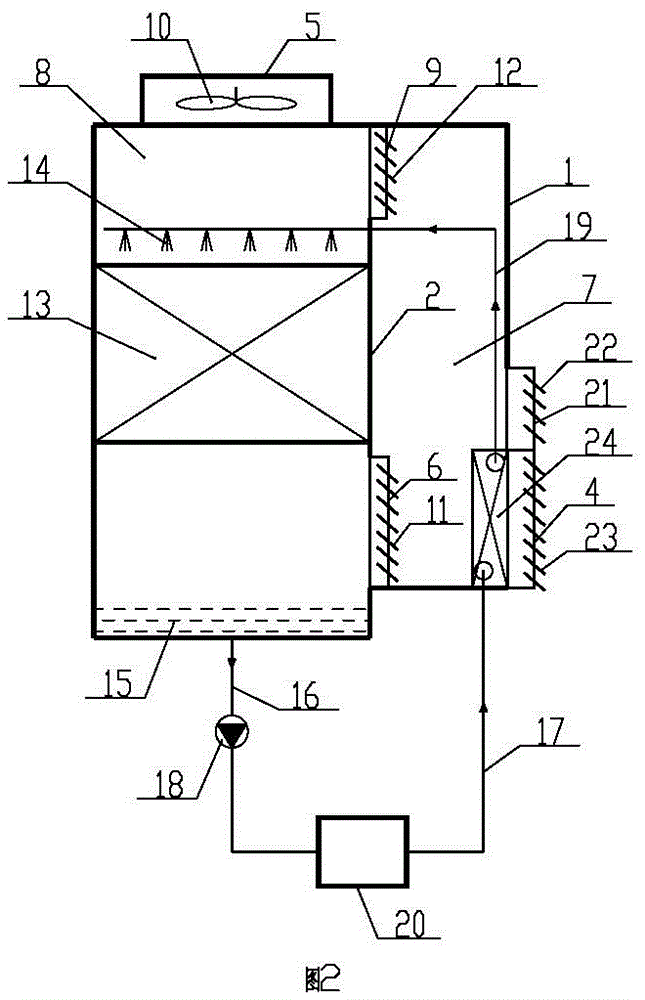
[0038] Embodiment 2: as attached figure 2 As shown, the difference between embodiment 2 and embodiment 1 is that the casing 1 above the first air inlet port 4 of embodiment 2 is provided with a second air inlet port 21, and the lower end of the second air inlet port 21 is connected to the first air inlet port 4. The upper ends of the first air inlet port 4 are adjacent to each other, and the second air inlet port 21 communicates with the lower air inlet 6 of the refrigeration device and the upper air inlet 9 of the refrigeration device through the air chamber 7; the first air inlet port 4 is provided with a first air volume switch device 23 , the second air volume switch device 22 is provided on the second air inlet port 21 .
Embodiment 3
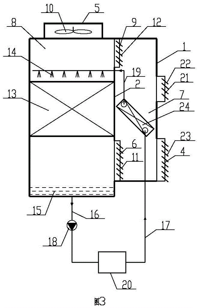
[0039] Embodiment 3: as attached image 3 As shown, the difference between embodiment 3 and embodiment 1 is that the housing 1 above the first air inlet port 4 of embodiment 3 is provided with a second air inlet port 21, and the lower end of the second air inlet port 21 is connected to the first air inlet port 4. There is a distance between the upper ends of the first air inlet port 4, and the second air inlet port 21 communicates with the lower air inlet 6 of the refrigeration device and the upper air inlet 9 of the refrigeration device through the air chamber 7; the first air inlet port 4 is provided with a first air volume The switch device 23, the second air volume switch device 22 is provided on the second air inlet port 21; the system return water surface heat exchange device 24 is obliquely placed in the air chamber 7, and is located between the first air inlet port 4 and the second air inlet port. between port 21. In Embodiment 3, the system backwater surface heat exc...
PUM
 Abstract
Description
Claims
Application Information
 - R&D
- Intellectual Property
- Life Sciences
- Materials
- Tech Scout
- Unparalleled Data Quality
- Higher Quality Content
- 60% Fewer Hallucinations
Browse by: Latest US Patents, China's latest patents, Technical Efficacy Thesaurus, Application Domain, Technology Topic, Popular Technical Reports.
© 2025 PatSnap. All rights reserved.Legal|Privacy policy|Modern Slavery Act Transparency Statement|Sitemap|About US| Contact US: help@patsnap.com


