
Surge current regulating circuit

A technology for adjusting circuits and inrush currents, applied in circuits, electrical components, electronic switches, etc., to solve problems such as system shutdown, inrush current size adjustment, reliability effects, etc.

Inactive Publication Date: 2014-10-15
WARECONN TECH SERVICE (TIANJIN) CO LTD
View PDF3 Cites 8 Cited by
  • Summary
  • Abstract
  • Description
  • Claims
  • Application Information

AI Technical Summary

Problems solved by technology

The surge current has a great impact on the reliability of the entire system, and even causes the system to stop working due to overcurrent protection. However, the current design of the surge current cannot adjust the magnitude of the surge current. devices have some limitations

Method used


Image

  • Surge current regulating circuit
  • Surge current regulating circuit

Examples


Embodiment Construction

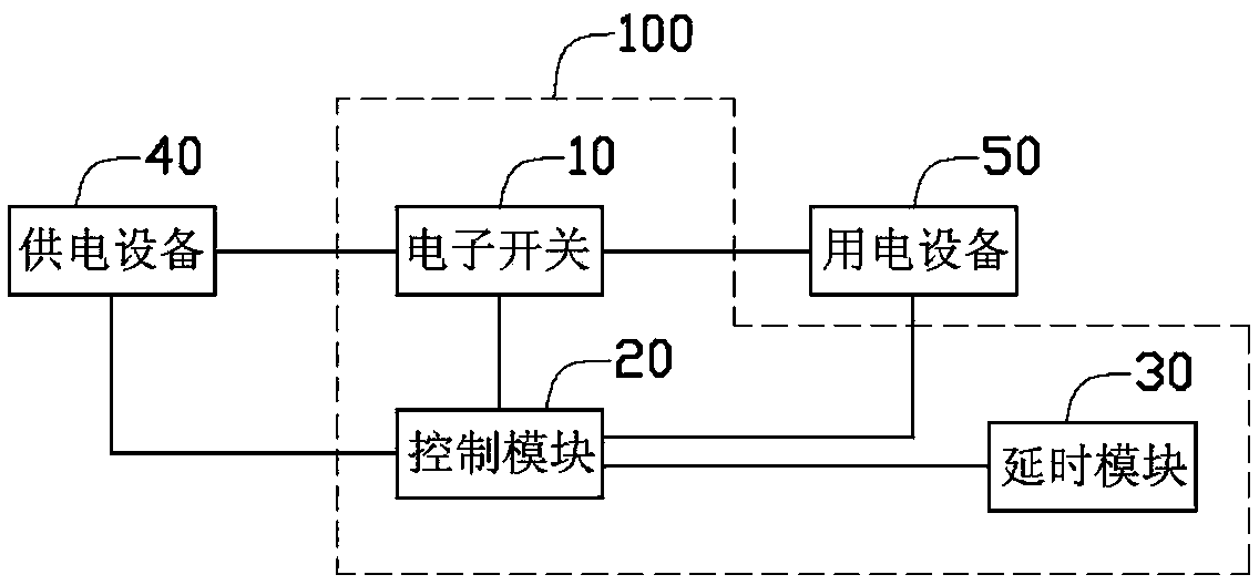
[0014] Please refer to figure 1 , the surge current regulating circuit 100 of the present invention is connected between the power supply equipment 40 and the electric equipment 50 , and a preferred embodiment of the regulating circuit 100 includes an electronic switch 10 , a control module 20 and a delay module 30 . A first end of the electronic switch 10 is connected to the control module 20 , a second end of the electronic switch 10 is connected to the power supply device 40 , and a third end of the electronic switch 10 is connected to the electric device 50 . The control module 20 delays outputting the control signal to the electronic switch 10 under the control of the delay module 30 .

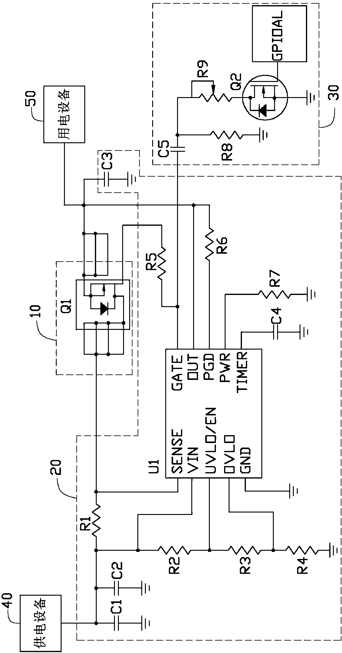
[0015] The delay module 30 includes a capacitor C5, a variable resistor R9 and a field effect transistor Q2, the gate of the field effect transistor Q2 is connected to a general input and output interface, and the drain of the field effect transistor Q2 passes through the variable resisto...


PUM


Abstract

The invention discloses a regulating circuit, which comprises a control module, a delay module and an electronic switch, wherein the control module is connected with power supply equipment and electric equipment, and is used for outputting a signal; the delay module is connected with the control module and the electronic switch respectively, and is used for adjusting the intensity of the signal received by the electronic switch to change the switch-on speed of the electronic switch; the first end of the electronic switch is connected with the control module and the delay module respectively; the second end of the electronic switch is connected with the power supply equipment; the third end of the electronic switch is connected with the electric equipment. By adopting the regulating circuit, the switch-on speed of the electronic switch can be controlled through the delay module and the control module, so that the aim of the regulating the surge current is fulfilled.

Description

technical field [0001] The invention relates to a surge current regulating circuit. Background technique [0002] Electronic products will generate inrush current at the moment when they are powered on, and the faster the opening speed of the electronic switch used to connect the power supply equipment and electronic equipment, the greater the inrush current value will be. The surge current has a great impact on the reliability of the entire system, and even causes the system to stop working due to overcurrent protection. However, the current design of the surge current cannot adjust the magnitude of the surge current. devices have some limitations. Contents of the invention [0003] In view of this, it is necessary to provide an adjustment circuit that can adjust the magnitude of the surge current. [0004] A surge current regulation circuit, comprising: [0005] A control module, connected between a power supply device and a power consumption device, when the power su...

Claims


Application Information

Patent Timeline
Patent Type & Authority Applications(China)
IPC IPC(8): G06F1/26
CPCH03K17/284H03K17/0822H03K17/22
Inventor 田波吴亢
Owner WARECONN TECH SERVICE (TIANJIN) CO LTD
Learn More