Positioning method, device and system

A positioning method and antenna system technology, applied to instruments, ticketing equipment, etc., can solve problems such as communication failure, car-following interference, and reduce the success rate of traffic opening, so as to achieve the effect of ensuring accuracy, avoiding car-following interference, and ensuring the success of traffic opening

Active Publication Date: 2017-02-08
SHENZHEN GENVICT TECH
View PDF5 Cites 0 Cited by
  • Summary
  • Abstract
  • Description
  • Claims
  • Application Information

AI Technical Summary

Problems solved by technology

In practical applications, due to the reflection and scattering of electromagnetic waves by the road surface and surrounding objects, it is difficult for the communication area between the RSU and the OBU to have a clear boundary in the longitudinal direction of the lane (that is, the direction of vehicle traffic). figure 2 In the fuzzy communication area marked by a triangle symbol, in the fuzzy communication area, when the passing vehicles are dense, it is easy to cause interference with the vehicle, and the communication between the RSU and the current OBU will often cause the RSU and the current OBU to be located on the adjacent OBU. The failure of communication reduces the success rate of traffic opening, especially when the speed of traffic opening is fast, the RSU and OBU are required to start communicating when they are far apart. In this way, the fuzzy communication area will be larger, and it is easier to cause interference with vehicles, further Reduce the success rate of opening traffic

Method used


Image

  • Positioning method, device and system
  • Positioning method, device and system
  • Positioning method, device and system

Examples


Embodiment 1

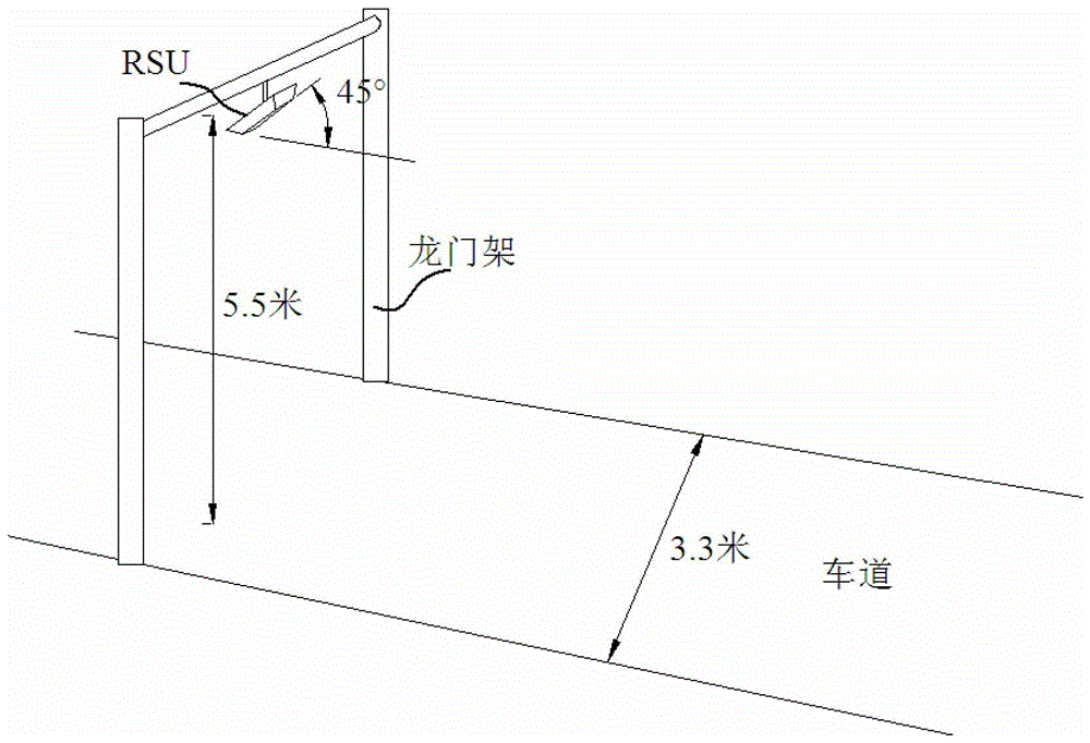
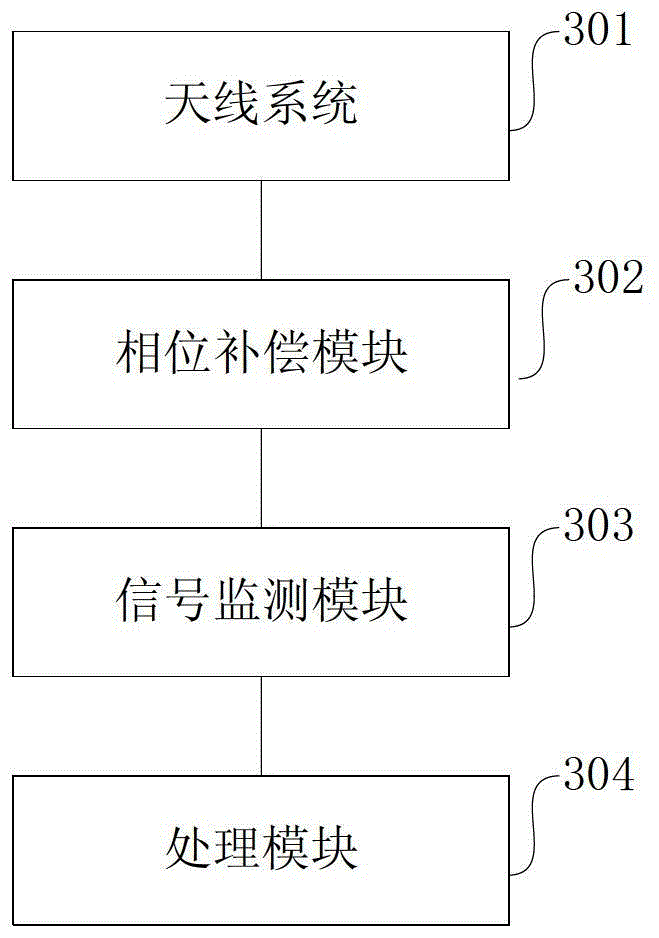
[0051] This embodiment 1 describes a positioning method, which is based on a positioning system for non-stop charging of vehicles driving on the lane, that is, the ETC system, including the OBU installed on the vehicle and the gantry installed at the entrance and exit of the toll station The RSU on the rack, where the RSU placement method can refer to figure 1 As shown, the positioning device of Embodiment 1 of the present application is integrated in the RSU. Through the positioning device and the OBU as the target point for interactive processing of positioning information, the azimuth of the vehicle can be obtained in a very short time, and in this very short time It is considered that the vehicle will not be displaced, so as to complete the angular positioning of the vehicle. In order to realize positioning, the structure of the above-mentioned positioning device can be as follows image 3 As shown, it mainly includes an antenna system 301, a phase compensation module 302...

Embodiment 2

[0066] The difference between this embodiment and Embodiment 1 mainly lies in:

[0067] Please refer to Figure 8 In the positioning device of the positioning system in this embodiment, the signal monitoring module 303 mainly includes a difference network 801 and a difference signal monitoring module 802 in order to monitor whether the compensated first signal and the second signal overlap. The difference network 801 is used to obtain the compensated first signal and the second signal, and perform difference processing on them to obtain a difference signal. The difference signal monitoring module 802 is used to determine whether the voltage of the difference signal processed by the difference network 801 maintains a value of 0 within a predetermined time after compensation, and if so, the compensated first signal and the second signal overlap. Taking a sinusoidal signal as an example, if the phase difference is fully compensated, at this time, the difference signal is 0 val...

Embodiment 3

[0077] The difference between this embodiment and Embodiment 1 mainly lies in:

[0078] Please refer to Figure 10 , in the positioning device of the positioning system of this embodiment, the phase compensation module 302 completes the above-mentioned phase difference by changing the compensation phase Compensation is mainly to connect the phase shifter 404 to the subsequent circuit of the second antenna 402, and perform phase shift processing on the second signal, and the others are similar.

[0079] Based on the positioning system of the third embodiment, the flow of the positioning method of the third embodiment is mainly as follows Figure 11 shown, including:

[0080] 1101, the first antenna 401 and the second antenna 402 receive the same wireless signal sent by the target point OBU, and correspondingly form the same wireless signal with the same amplitude but with a phase difference in the horizontal direction The first signal and the second signal of the first rou...


PUM


Abstract

The application discloses a positioning method, device and system. The positioning method mainly adopts two antennas of the same specification which are arranged at an interval to receive the same wireless signal sent out from a target point, a first path of signal and a second path of signal which have a phase difference are formed correspondingly, the phase difference is compensated with a varying compensation phase, when the compensated first path of signal and second path of signal are superposed, the current compensation phase that enables superposition of the compensated first path of signal and second path of signal determines an azimuth angle of the target point, since determining of the azimuth angle is completed in an extremely short time, the target point can be regarded as in a stationary state within the extremely short time, thus accurate positioning of the target point in angle can be completed, accuracy of communication with the target point after positioning is ensured, and when the positioning method is applied to an ETC system, vehicle following interference can be prevented, and vehicle passing is ensured.

Description

technical field [0001] The present application relates to the field of intelligent traffic signal processing, in particular to a positioning method, device and system. Background technique [0002] Electronic Toll Collection (ETC) is a specific application of Intelligent Transportation System (ITS). The ETC system is mainly composed of roadside equipment (Road-Side Units, RSU) and on-board equipment (On-Board Units, OBU). Usually, such as figure 1 As shown, the RSU is installed on the gantry at the entrance and exit of the toll station, above the driveway, the typical installation height is 5.5 meters, the installation angle is 45° between the main surface and the ground, and the width of the driveway is generally 3.3 meters; OBU installation on the front windshield of the vehicle. When the vehicle passes through the lane, the OBU installed on the vehicle is awakened by the RSU, communicates with the RSU and completes the information interaction process of non-stop chargi...

Claims


Application Information

Patent Timeline
Patent Type & Authority Patents(China)
IPC IPC(8): G07B15/06
Inventor 殷忠良徐根华周青呈
Owner SHENZHEN GENVICT TECH
Why Eureka
Try Eureka