Antenna structure

An antenna structure and wireless signal technology, applied to antennas, radiating element structure forms, and devices that enable antennas to work in different bands at the same time, can solve the problems of size and internal space reduction, antenna design space compression, etc.

Inactive Publication Date: 2014-10-15
SHENZHEN FUTAIHONG PRECISION IND CO LTD +1
View PDF4 Cites 1 Cited by
  • Summary
  • Abstract
  • Description
  • Claims
  • Application Information

AI Technical Summary

Problems solved by technology

However, with the diversification of wireless products, the required communication frequency bands are gradually increasing, while the size and internal space of these communication products are gradually shrinking, and the design space of the relative antenna is also compressed
The general antenna structure includes a feed-in terminal and a radiator, but how to design a multi-band antenna in a limited space will be a big challenge

Method used


Image

  • Antenna structure
  • Antenna structure
  • Antenna structure

Examples


Embodiment Construction

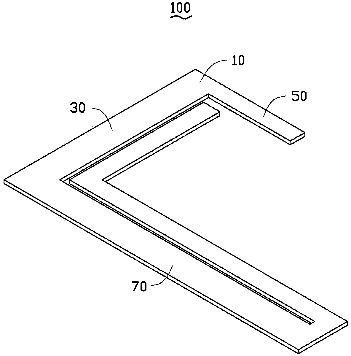
[0012] see figure 1 , a preferred embodiment of the present invention provides an antenna structure 100, which is applied to wireless communication devices such as mobile phones and tablet computers. The antenna structure 100 includes a feeding end 10 , a first radiator 30 , a second radiator 50 and a third radiator 70 .

[0013] The feed end 10 is electrically connected to a signal feed point (not shown) on the circuit board of the wireless communication device, so as to feed current to the antenna structure 100 .

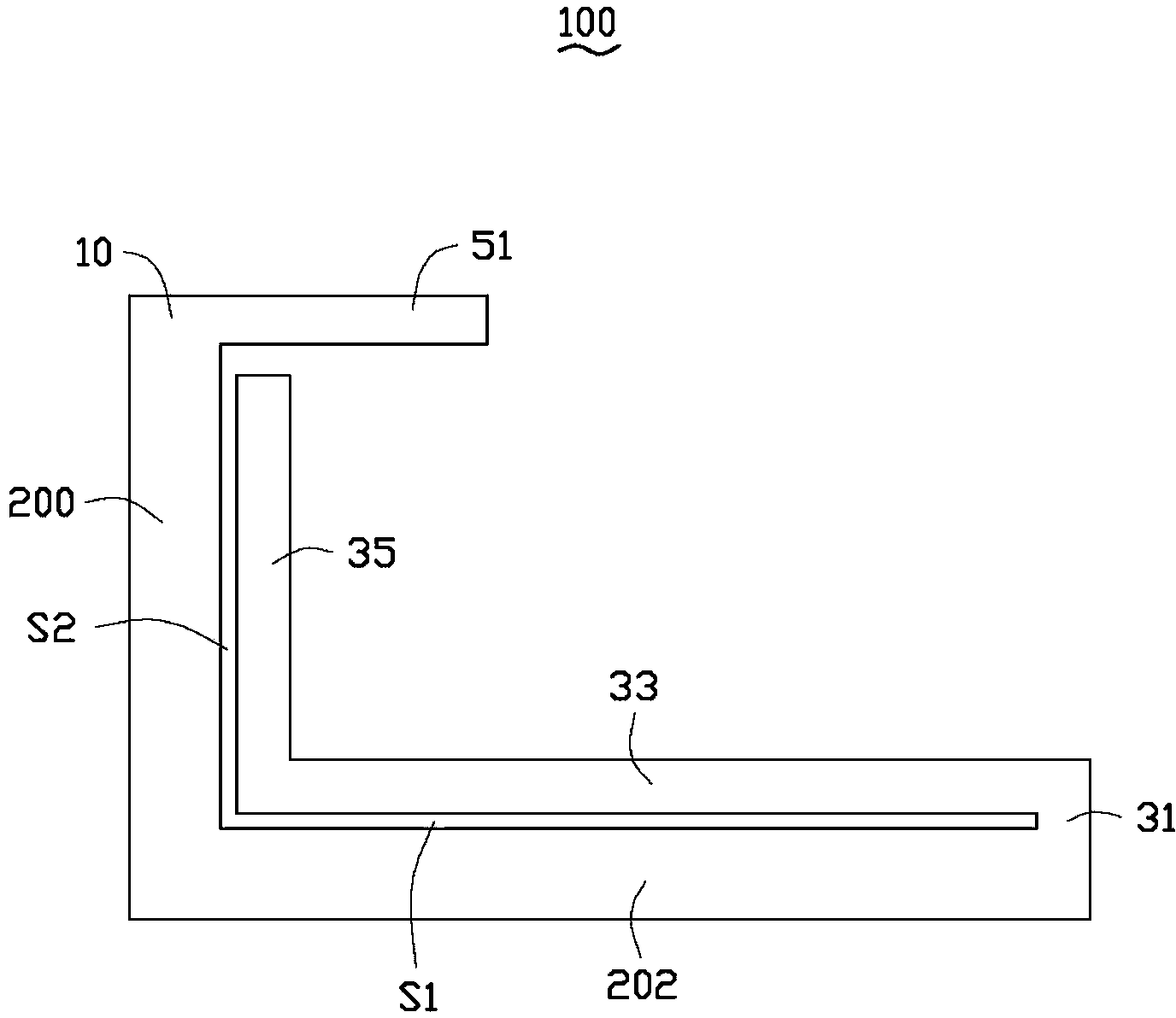
[0014] Please also refer to figure 2 , the first radiator 30 is connected to the feeding end 10 , and includes a first sharing section 200 , a second sharing section 202 , a first extension section 31 , a second extension section 33 and a third extension section 35 connected in sequence. In this embodiment, the first sharing section 200 , the second sharing section 202 , the first extension section 31 , the second extension section 33 and the third extension se...


PUM


Abstract

The invention provides an antenna structure, which comprises a feed-in end, a first radiation body and an extension section. The first radiation body comprises a first sharing section, a second sharing section, a first extension section, a second extension section and a third extension section connected in sequence. The first sharing section and the extension section are connected with the feed-in end. The first radiation body is used for receiving and sending wireless signals with the first center frequency. The first sharing section and the extension section form a second radiation body used for receiving and sending wireless signals with the second center frequency. The first sharing section and the second sharing section form a third radiation body used for receiving and sending wireless signals with the third center frequency. According to the antenna structure, the first sharing section is shared via the first radiation body and the second radiation body, the first sharing section and the second sharing section are shared via the first radiation body and the third radiation body, the size of the antenna is reduced, and miniaturization development of a wireless communication device is facilitated.

Description

technical field [0001] The invention relates to an antenna structure, in particular to an antenna structure capable of receiving multi-band wireless signals. Background technique [0002] With the vigorous development of wireless communication, it has changed our life and brought various conveniences, and therefore various wireless communication products have appeared. However, with the diversification of wireless products, the required communication frequency bands are gradually increasing, while the size and internal space of these communication products are gradually shrinking, and the design space of the corresponding antenna is also compressed. A general antenna structure includes a feed-in terminal and a radiator, but how to design a multi-band antenna in a limited space will be a big challenge. Contents of the invention [0003] In view of the above circumstances, it is necessary to provide an antenna structure capable of receiving multi-band wireless signals and o...

Claims


Application Information

Patent Timeline
Patent Type & Authority Applications(China)
IPC IPC(8): H01Q1/36H01Q5/01
Inventor 李义杰林彦辉
Owner SHENZHEN FUTAIHONG PRECISION IND CO LTD
Why Eureka
Try Eureka