Passivity-based control method for speed-senseless interpolating permanent magnet synchronous motor

A permanent magnet synchronous motor, no speed sensor technology, applied in motor generator control, electronic commutation motor control, control system and other directions, can solve the problem of unsuitable interpolated permanent magnet synchronous motor, etc., to achieve good steady-state accuracy and dynamic performance, improved estimation accuracy, and easy-to-implement effects

Active Publication Date: 2014-10-15
LIAONING TECHNICAL UNIVERSITY
View PDF3 Cites 13 Cited by
  • Summary
  • Abstract
  • Description
  • Claims
  • Application Information

AI Technical Summary

Problems solved by technology

However, this method is not suitable for direct application to interpolated permanent magnet synchronous motors, because the rotor position information is not only included in the back electromotive force but also related to its alternating and direct axis inductance.

Method used


Image

  • Passivity-based control method for speed-senseless interpolating permanent magnet synchronous motor
  • Passivity-based control method for speed-senseless interpolating permanent magnet synchronous motor
  • Passivity-based control method for speed-senseless interpolating permanent magnet synchronous motor

Examples


Embodiment Construction

[0028] The specific embodiments of the present invention will be described in detail below in conjunction with the accompanying drawings.

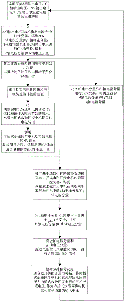
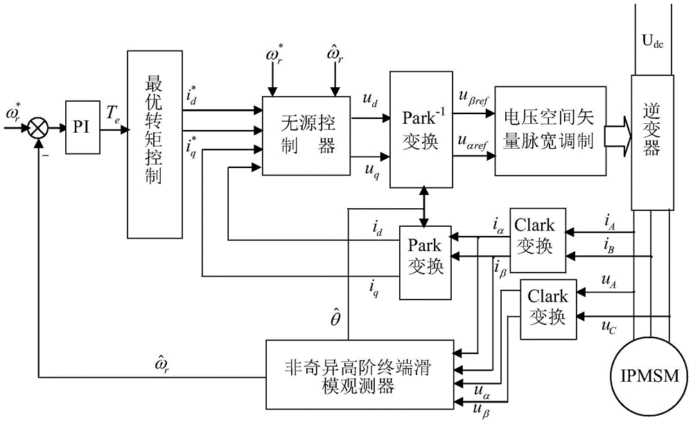
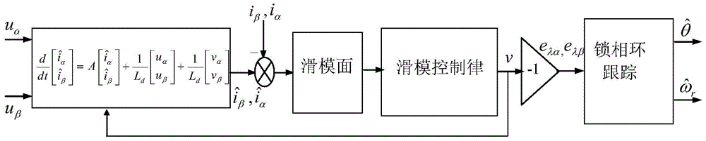
[0029] A speed sensorless interpolation permanent magnet synchronous motor passive control method, the principle is as follows figure 2 As shown, the flow chart of the method is as follows figure 1 shown, including the following steps:

[0030] Step 1: During the operation of the interpolated permanent magnet synchronous motor, collect the output voltage of phase A, the output voltage of phase C, the output current of phase A and the output current of phase B in real time, and set the desired motor of the interpolated permanent magnet synchronous motor. Rotating speed

[0031] Step 2: Perform Clark transformation on the output current of phase A and the output current of phase B to obtain the α-axis current component i of the interpolated permanent magnet synchronous motor in the α-β stationary coordinate system α and β-axis current ...


PUM


Abstract

The invention relates to a passivity-based control method for a speed-senseless interpolating permanent magnet synchronous motor. The passivity-based control method comprises the following steps of: setting a desired motor rotational speed, establishing a non-singular high-order terminal sliding-mode observer to estimate a motor rotational speed estimated value and a motor rotor angular displacement estimated value, evaluating the difference between the desired motor rotational speed and the motor rotational speed estimated value, carrying out PI adjustment, evaluating a desired electromagnetic torque, obtaining a desired d-axis current component and a desired q-axis current component through optimal torque control, establishing a passive controller for the interpolating permanent magnet synchronous motor, based on a port controlled Hamiltonian system model, evaluating a d-axis voltage component and a q-axis voltage component, carrying out pack-1 transform on the d-axis voltage component and the q-axis voltage component to obtain an alpha-axis voltage component and a reference beta-axis voltage component, and carrying out voltage space vector pulse-width modulation on the alpha-axis voltage component and the reference beta-axis voltage component to obtain six paths of drive pulse signals. The control method enables the whole system to be provided with good steady accuracy and dynamic performance.

Description

technical field [0001] The invention belongs to the technical field of motor control, and in particular relates to a passive control method for an interpolated permanent magnet synchronous motor without a speed sensor. Background technique [0002] The interpolated permanent magnet synchronous motor has been widely used in industrial and mining enterprises due to its advantages of high power density, high operating efficiency and reliable structure. However, it is affected by uncertainties such as motor parameter changes, load disturbances, and unmodeled objects, and the mechanical speed sensors currently used increase costs and reduce system reliability. To achieve high-performance regulation of interpolated permanent magnet synchronous motors Therefore, it is necessary to design advanced control methods on the basis of accurately obtaining rotor position and speed information. [0003] In recent years, for surface-mounted permanent magnet synchronous motors, the counter e...

Claims


Application Information

Patent Timeline
Patent Type & Authority Applications(China)
IPC IPC(8): H02P21/14
Inventor 侯利民赵金鹏臧东蔡柯
Owner LIAONING TECHNICAL UNIVERSITY
Why Eureka
Try Eureka