Cooling fin and electric power conversion device comprising same

A technology of a heat sink and an air inlet is applied in the field of heat sinks and power conversion devices equipped with the heat sinks, and can solve problems such as increased cost and the like

Active Publication Date: 2014-10-15
FUJI ELECTRIC CO LTD
View PDF5 Cites 2 Cited by
  • Summary
  • Abstract
  • Description
  • Claims
  • Application Information

AI Technical Summary

Problems solved by technology

[0020] If the above-mentioned measures (a) to (d) are taken, there are problems such as increase in cost and enlargement of the entire device

Method used


Image

  • Cooling fin and electric power conversion device comprising same
  • Cooling fin and electric power conversion device comprising same
  • Cooling fin and electric power conversion device comprising same

Examples


Embodiment approach 1

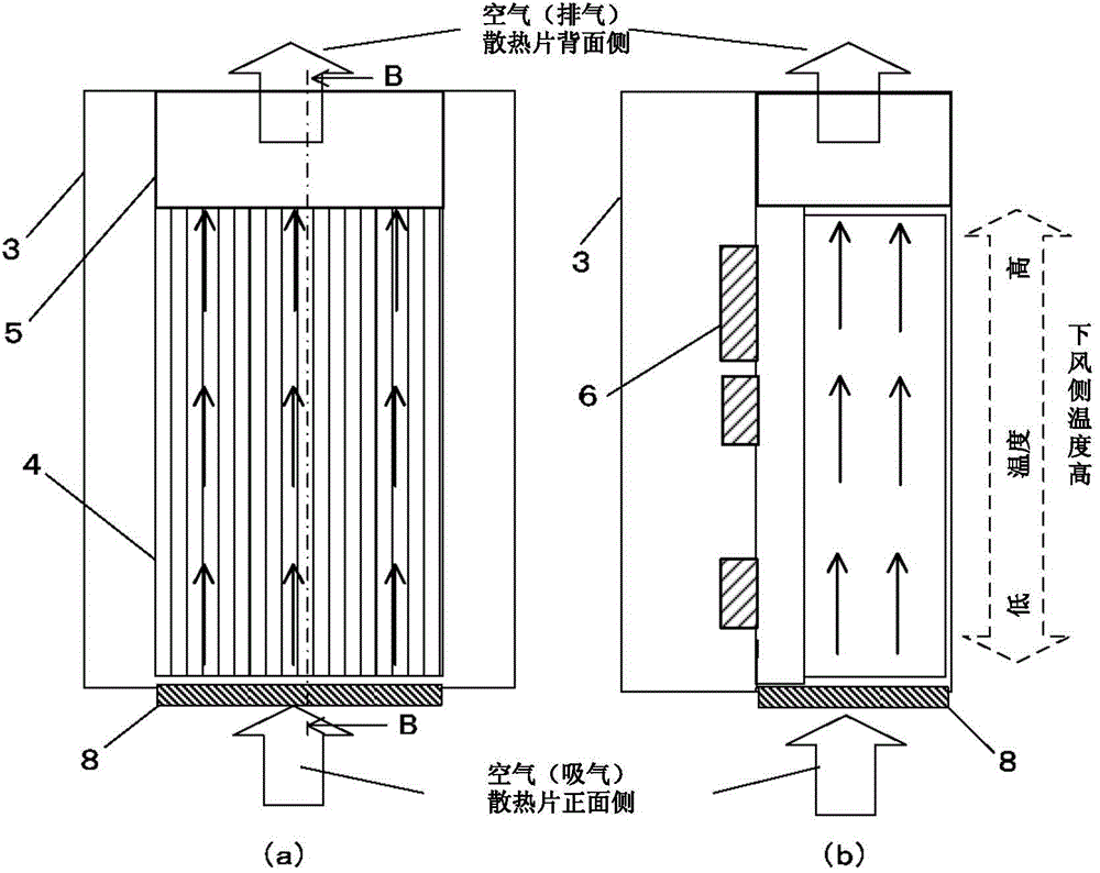
[0043] Figure 4 It is a figure which shows the structure of the heat sink of Embodiment 1 of this invention. in addition, Figure 5 It is a figure explaining the effect|action of the heat sink of Embodiment 1 of this invention.

[0044] exist Figure 4 and Figure 5 Among them, the structure of the heat sink according to Embodiment 1 of the present invention is not only provided with an air inlet on the front side of the heat sink, but also provided with a plurality of air inlets on any side or bottom in the middle from the front of the heat sink to the back of the heat sink. Inhalation port, able to inhale from all inspiratory ports at the same time.

[0045] That is, in Figure 4 (a), (b) and Figure 5In (a) and (b), on the heat sink 4, not only the air intake 8 on the front side of the heat sink is provided, but also a plurality of air intakes are provided on any side from the front of the heat sink to the back of the heat sink. 9. An air intake 10 is also provided ...

Embodiment approach 2

[0060] Figure 9 It is a figure which shows the structure of the heat sink of Embodiment 2 of this invention. in addition, Figure 10 It is a figure explaining the effect|action of the heat sink of Embodiment 2 of this invention.

[0061] exist Figure 9 and Figure 10 In the heat sink according to Embodiment 2 of the present invention, like the heat sink according to Embodiment 1 of the present invention described above, there are not only air inlets on the front side of the heat sink, but also any intermediate position from the front of the heat sink to the rear of the heat sink. A plurality of suction ports are newly arranged on the side or the bottom surface of the utility model, and air can be sucked from all the suction ports at the same time.

[0062] That is, in Figure 9 (a), (b) and Figure 10 In (a) and (b), a plurality of air inlets 9 are provided on any side surface from the front of the heat sink to the middle of the back of the heat sink, and a notch is pr...


PUM


Abstract

The present invention provides a cooling fin which is not only provided with an air suction port at a right side of the cooling fin, but also additionally provided with a plurality of air suction ports on any side surface in the middle from the right side of the cooling fin to a back side of the cooling fin, and additionally provided with air suction ports on any bottom surface in the middle from the right side of the cooling fin to the back side of the cooling fin, so as to obtain the air newly sucked from the air suction ports between an upstream side and a downstream side of the cooling fin. Air can be sucked from the plurality of air suction ports provided at any side surface or bottom surface in the middle from the right side of the cooling fin to the back side of the cooling fin, therefore, external fresh air is sucked from any position inside the cooling fin, turbulent flow may occur due to collision of two air flow vectors formed by the air from the air suction port at one side towards the back side and the air sucked from the other plurality of air suction ports in the direction perpendicular to the direction of the above-mentioned air.

Description

technical field [0001] The present invention relates to a heat sink and a power conversion device including the heat sink. Background technique [0002] In general, a power conversion device is composed of the following parts: an input transformer; a plurality of unit inverter units connected to the secondary side of the transformer to form an inverter circuit; Switchboard in closed panel. For example, in the power conversion device described in Patent Document 1 below, the input transformer 4 is housed in the transformer board 1 , and a plurality of (six in the illustrated example) unit inverters arranged in a vertical order are housed in the converter board 2 . In the inverter unit 5 , a control unit 6 and an output cable 7 are housed in the control / output tray 3 . [0003] In addition, the transformer panel 1 and the converter panel 2 are provided with cooling fans 8, 9 on the top of the panel, and the converter panel 2 is introduced into the air inlet 2a-1 with a filte...

Claims


Application Information

Patent Timeline
IPC IPC(8): H05K7/20H02M7/00
Inventor 中岛健裕
Owner FUJI ELECTRIC CO LTD
Why Eureka
Try Eureka