Electricity meter, method for detecting theft of electricity meter, and power supply system
A technology of electric energy metering device and detection method, which is applied in the direction of measuring device, selecting device, measuring electric variables, etc., and can solve the problems of inability to detect electricity theft and use by electric thieves
- Summary
- Abstract
- Description
- Claims
- Application Information
AI Technical Summary
Problems solved by technology
Method used
Image

Examples
Embodiment approach 1
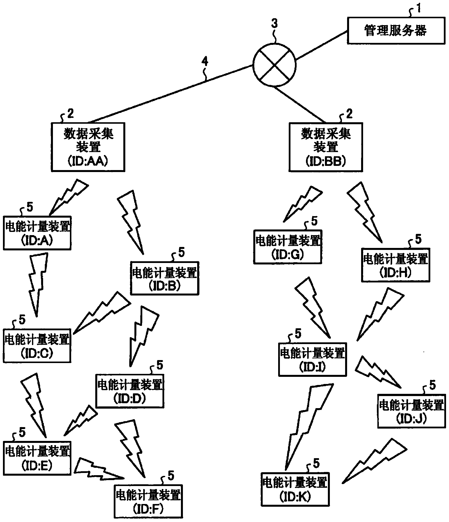
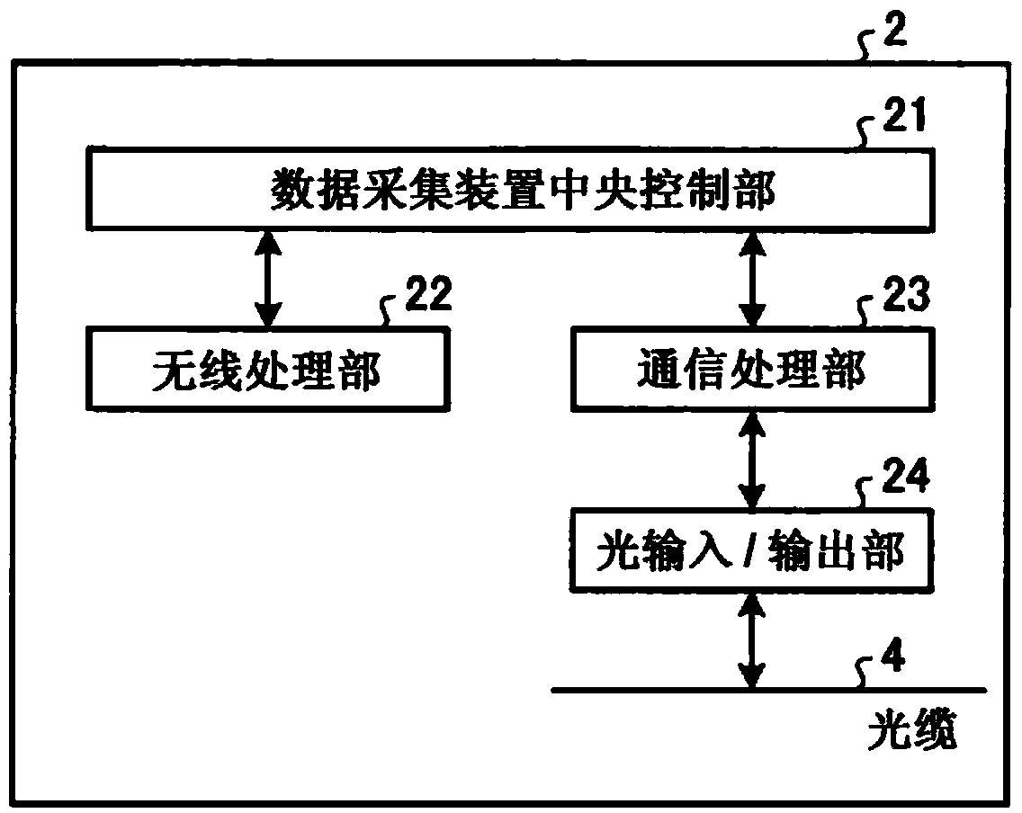
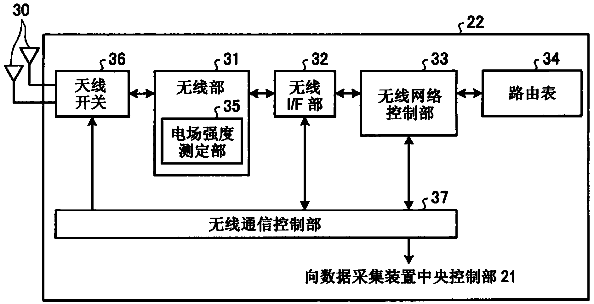
[0028] refer to Figure 1 to Figure 11 Embodiment 1 of the electric energy metering device concerning this invention is demonstrated. In addition to the original function of the energy metering device, that is, the function of measuring and measuring the power supply and power consumption to installed users (households, factories, etc.), the energy metering device of this embodiment also has a wireless The communication function can form a wireless mesh network through the wireless communication function. In addition, information such as the measured electric power is sent to the data acquisition device via the wireless mesh network. When receiving / transmitting various information with other devices having a communication function (data collection devices, other energy metering devices, etc.), it is also performed via a wireless mesh network.
[0029] figure 1 It is a diagram showing a configuration example of Embodiment 1 of a wireless mesh system including a wireless mesh...
Embodiment approach 2
[0071] An electric energy metering device according to Embodiment 2 will be described. In addition, the structure of the communication network formed by the electric energy metering device, the wireless mesh system, the data acquisition device, and the electric energy metering device is the same as that of Embodiment 1 (refer to Figure 1 ~ Figure 4 ).
[0072] use Figure 12 The theft detection operation performed by the electric energy metering device 5 of the present embodiment will be described. Figure 12 It is a figure which shows an example of the theft detection procedure by the electric energy metering apparatus 5 of Embodiment 2. For the theft detection operation described in Embodiment 1 ( Figure 5 ) for general processing, labeling and Figure 5 Same step number, and omit description.
[0073] The theft detection operation performed by the electric energy metering device 5 of the present embodiment is performed by inserting step S31 between steps S12 and S13 ...
Embodiment approach 3
[0085] An electric energy metering device according to Embodiment 3 will be described. In addition, the structure of the communication network formed by the electric energy metering device, the wireless mesh system, the data acquisition device, and the electric energy metering device is the same as that of Embodiment 1 (refer to Figure 1 ~ Figure 4 ).
[0086] use Figure 16 The theft detection operation performed by the electric energy metering device 5 of the present embodiment will be described. Figure 16 It is a figure which shows an example of the theft detection procedure by the electric energy metering apparatus 5 of Embodiment 3. For the theft detection action described in Embodiments 1 and 2 ( Figure 5 , Figure 12 ) for general processing, labeling and Figure 5 , Figure 12 Same step number, and omit description.
[0087] The theft detection operation performed by the electric energy metering device 5 of the present embodiment is realized by inserting step...
PUM
 Abstract
Description
Claims
Application Information
 - R&D Engineer
- R&D Manager
- IP Professional
- Industry Leading Data Capabilities
- Powerful AI technology
- Patent DNA Extraction
Browse by: Latest US Patents, China's latest patents, Technical Efficacy Thesaurus, Application Domain, Technology Topic.
© 2024 PatSnap. All rights reserved.Legal|Privacy policy|Modern Slavery Act Transparency Statement|Sitemap