Mold replacing device of fuel tank assembly
An integrated device and oil tank passing technology, which is applied in the field of oil tank integrated mold change device, can solve problems such as mold tilt and unsafety, and achieve the effects of not easy to tilt, simple operation, and improved mold change efficiency
- Summary
- Abstract
- Description
- Claims
- Application Information
AI Technical Summary
Problems solved by technology
Method used
Image

Examples
Embodiment Construction
[0016] The present invention will be described in further detail below in conjunction with the accompanying drawings.
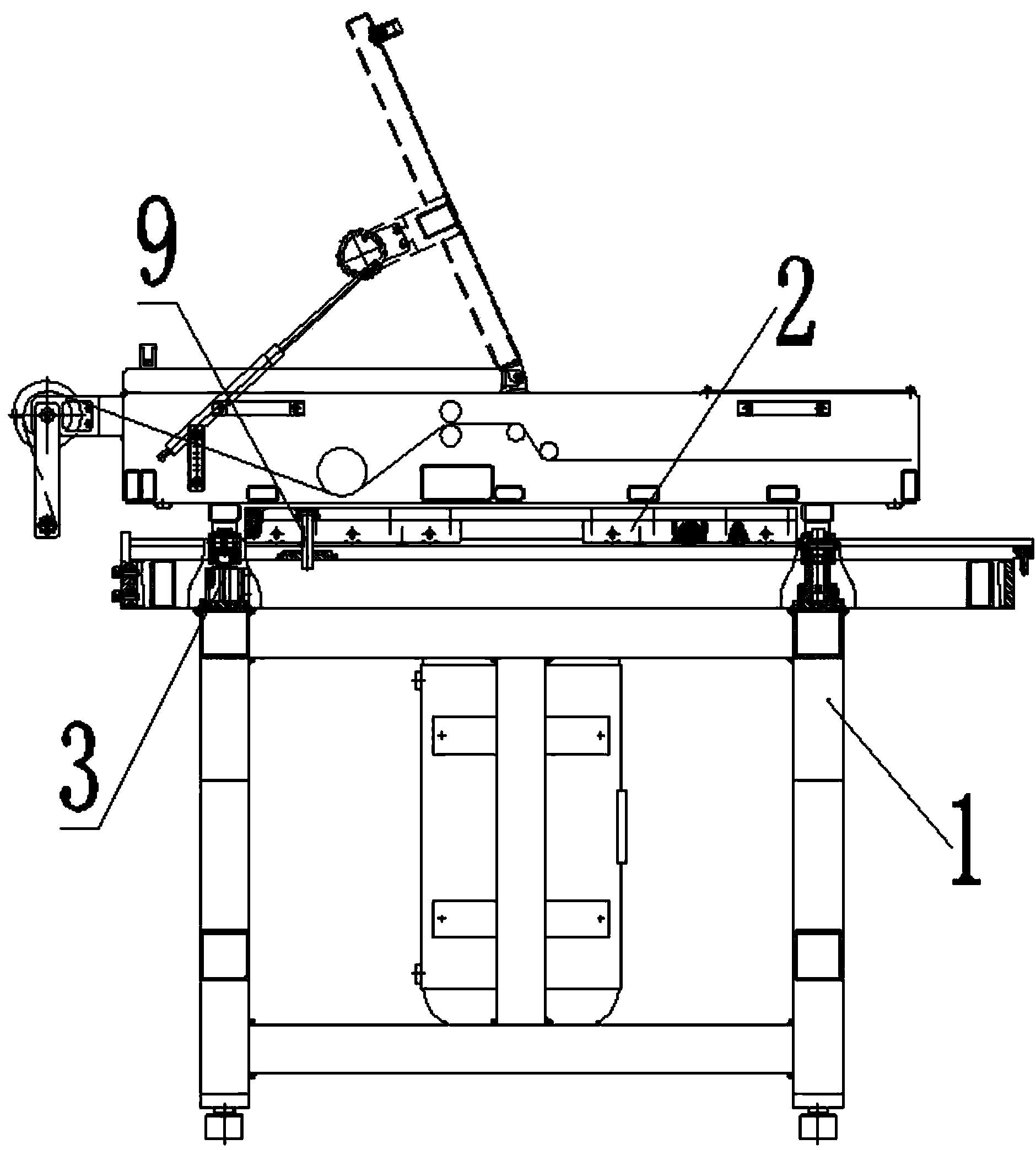
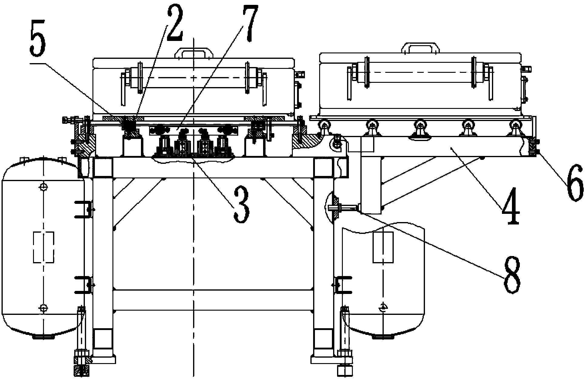
[0017] Such as figure 1 and figure 2 as shown, figure 1 It is a schematic structural diagram of the front view of the integrated mold change device through the fuel tank of the present invention, figure 2 It is a side view structural schematic diagram of the oil tank integrated mold changing device of the present invention.
[0018] An integrated mold changing device for passing through a fuel tank, comprising a mold changing bracket 1, a mold changing trolley 2, two supporting arms 3 passing through a fuel tank and two moving arms 4 passing through a fuel tank, the two supporting arms 3 passing through a fuel tank are respectively arranged on the At both ends of the die change bracket 1, the fuel tank moving arm 4 is arranged on one side of the die change bracket 1 corresponding to the fuel tank support arm 3, and two rows of rollers are arranged on bot...
PUM
 Abstract
Description
Claims
Application Information
 - Generate Ideas
- Intellectual Property
- Life Sciences
- Materials
- Tech Scout
- Unparalleled Data Quality
- Higher Quality Content
- 60% Fewer Hallucinations
Browse by: Latest US Patents, China's latest patents, Technical Efficacy Thesaurus, Application Domain, Technology Topic, Popular Technical Reports.
© 2025 PatSnap. All rights reserved.Legal|Privacy policy|Modern Slavery Act Transparency Statement|Sitemap|About US| Contact US: help@patsnap.com