Improved hydraulic fluid heating using hydraulic fan reversal

A technology of hydraulic fluid and fan, which is applied in the field of hydraulic systems and can solve problems such as long periods of time

Active Publication Date: 2017-12-22
DEERE & CO
View PDF5 Cites 0 Cited by
  • Summary
  • Abstract
  • Description
  • Claims
  • Application Information

AI Technical Summary

Problems solved by technology

However, this ramp-up cycle may require a longer period of time, such as an hour or more

Method used


Image

  • Improved hydraulic fluid heating using hydraulic fan reversal
  • Improved hydraulic fluid heating using hydraulic fan reversal
  • Improved hydraulic fluid heating using hydraulic fan reversal

Examples


Embodiment Construction

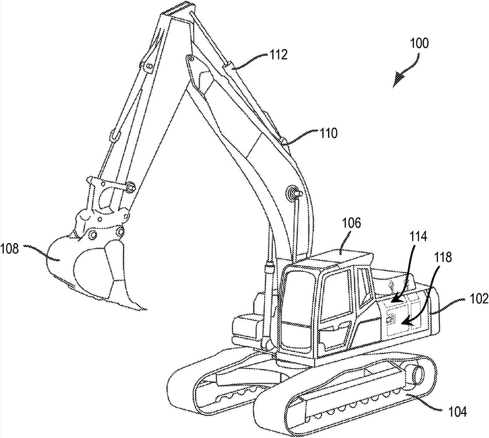
[0013] First refer to figure 1 , a work vehicle 100 in the form of an excavator is provided. Although vehicle 100 is shown and described herein as an excavator, for example, vehicle 100 may also be a loader, bulldozer, motor grader, or other construction, farm, or utility vehicle.

[0014] Vehicle 100 includes a chassis 102 . At least one traction device 104 , shown as a plurality of tracks, is arranged to support the chassis 102 on the ground. although figure 1 The traction means 104 is in the form of tracks, although the traction means 104 could also be in the form of wheels, for example, and still be within the scope of the present disclosure. Chassis 102 defines housing and protection of engine 116 ( figure 2 ) of the engine room 114. In use, engine 116 powers traction device 104 to propel chassis 102 over the ground.

[0015] Vehicle 100 also includes an operator cab 106 supported by chassis 102 that houses and protects an operator of vehicle 100 . Operator cab 10...


PUM


Abstract

The invention relates to a work vehicle comprising a cooling system and at least one hydraulic brake receiving hydraulic fluid, the cooling system causing said hydraulic fluid to go faster by directing air from an engine compartment through the hydraulic fluid in a reverse direction to heat said hydraulic fluid heating up.

Description

technical field [0001] The present disclosure relates to hydraulic systems of work vehicles. More specifically, the present disclosure relates to a hydraulic system that uses hydraulic fan reversal to facilitate improved hydraulic fluid heating of a work vehicle, and methods of using the same. Background technique [0002] During initial startup and operation of the work vehicle, the hydraulic fluid of the work vehicle may be relatively cold, especially when the work vehicle is operating in colder weather. For example, cold hydraulic fluid may be relatively viscous, which reduces the responsiveness of the hydraulic functions of the work vehicle, reduces hydraulic efficiency due to higher pressure drops of the work vehicle, and causes problems with power control of the work vehicle. When the cold hydraulic fluid finally warms up to normal operating temperature and becomes less viscous, the work vehicle can work and move properly. However, this ramp-up cycle may require a lo...

Claims


Application Information

Patent Timeline
Patent Type & Authority Patents(China)
IPC IPC(8): F15B21/04E02F9/22E02F3/85F15B21/0427F15B21/0423
CPCE02F9/2095F15B21/0427F15B21/0423E02F9/22F01P3/18F01P11/10B66C13/22
Inventor 兰斯·罗伯特·夏洛克
Owner DEERE & CO
Why Eureka
Try Eureka