Method for united correction of MIMO radar transceiving array errors

An array error, radar transceiver technology, applied to radio wave measurement systems, instruments, etc., can solve problems such as array flow pattern deviation, machining error, disturbance, etc., achieve the effect of realizing amplitude and phase error, improving correction accuracy, and realizing correction

Inactive Publication Date: 2014-10-22
UNIV OF ELECTRONICS SCI & TECH OF CHINA
View PDF5 Cites 34 Cited by
  • Summary
  • Abstract
  • Description
  • Claims
  • Application Information

AI Technical Summary

Problems solved by technology

[0003] In the MIMO radar system, the estimation of signal direction of arrival (DOA) usually adopts the high-resolution spectrum estimation method represented by the multiple signal classification method (MUSIC). Although this type of method has high resolution and estimation accuracy, but The premise of use is that the array flow pattern is accurately known. Due to the influence of various non-ideal factors, such as machining errors, inconsistent receiving channels, and array element mutual coupling, etc., the array flow pattern will have a certain degree of deviation and disturbance. As a result, the performance of the high-resolution spectral estimation method will seriously deteriorate, or even fail.

Method used


Image

  • Method for united correction of MIMO radar transceiving array errors
  • Method for united correction of MIMO radar transceiving array errors
  • Method for united correction of MIMO radar transceiving array errors

Examples


Embodiment Construction

[0037] The technical solutions of the present invention will be described in detail below in conjunction with the accompanying drawings.

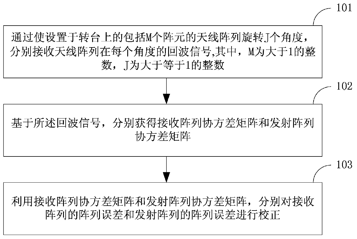
[0038] The joint correction method of the MIMO radar transceiver array error of the present application includes: by rotating the antenna array comprising M array elements arranged on the turntable by J angles, respectively receiving the echo signals of the antenna array at each angle, wherein, M is an integer greater than 1, and J is an integer greater than or equal to 1; based on the echo signal, a receiving array covariance matrix and a transmitting array covariance matrix are respectively obtained; using the receiving array covariance matrix and the transmitting array covariance matrix, respectively The array errors of the receive array and the array errors of the transmit array are corrected.

[0039] By obtaining the echo signal of the antenna array, and using the echo signal to construct the covariance matrix of the receiving matrix ...


PUM


Abstract

The invention discloses a method for united correction of MIMO radar transceiving array errors, wherein the method can improve array error correction precision. Echo signals of an antenna array are obtained, the echo signals are utilized to construct a receiving array covariance matrix and a transmitting array covariance matrix, the covariance matrixes of both a receiving array and a transmitting array are utilized to respectively correct the received and transmitted array errors, angular measurement inaccuracy caused by array errors is avoided, and the array errors of the receiving array and the transmitting array can be simultaneously corrected; orientation dependence occurs in an array guiding vector due to the array errors in collection, the antenna array rotates through J angles by enabling the antenna array comprising M array elements to be arranged on a turntable, the echo signals of the antenna array at each angle are respectively received, sample data of plenty of orientation angles of a plurality of orientations can be collected, and array error correction precision is improved. The method is suitable for being popularized and applied in the field of array signal processing.

Description

technical field [0001] The invention relates to the field of array signal processing, in particular to a joint correction method for MIMO radar transceiver array errors. Background technique [0002] MIMO (Multiple-Input Multiple-Output) radar is a multi-channel radar system, including a multi-element antenna structure, using multiple antennas to transmit signals, and using multiple antennas to receive echoes. The radar signal form And the system constitutes flexible and easy to expand. At the transmitting end of the MIMO radar, each array element (or sub-array) transmits mutually orthogonal signal waveforms omnidirectionally. Since the orthogonal waveforms cannot be coherently superimposed in space, a wide transmitting beam will be formed, thereby making the signal anti-intercept ability enhanced. At the receiving end of the MIMO radar, the echo signal is synthesized by the delay of all signals, and the orthogonal components in the echo signal are separated by a matched f...

Claims


Application Information

Patent Timeline
Patent Type & Authority Applications(China)
IPC IPC(8): G01S7/40
CPCG01S7/4008G01S7/4021
Inventor 钱江吴琪李道通刘剑刚贾勇沈炀黄聪
Owner UNIV OF ELECTRONICS SCI & TECH OF CHINA
Why Eureka
Try Eureka