Laser frequency shift detecting method and device with dual-cavity F-P interferometer which is formed on the basis of polarization maintaining optical fibers
What is Al technical title?
Al technical title is built by PatSnap Al team. It summarizes the technical point description of the patent document.
A polarization-maintaining optical fiber and detection equipment technology, applied in the field of optical detection, can solve the problems of reducing the signal-to-noise ratio of frequency discrimination, vibration, environmental temperature and humidity, and high manufacturing costs, so as to achieve mass production and energy efficiency The effect of high utilization rate and simple method
Active Publication Date: 2014-10-22
UNIV OF SCI & TECH OF CHINA
View PDF6 Cites 10 Cited by
Summary
Abstract
Description
Claims
Application Information
AI Technical Summary
This helps you quickly interpret patents by identifying the three key elements:
Problems solved by technology
Method used
Benefits of technology
Problems solved by technology
[0009] The object of the present invention is: in the double-edge Doppler frequency shift detection technology, the double-edge is realized by using a multi-channel F-P interferometer, which has high manufacturing cost and is greatly affected by vibration, ambient temperature and humidity, and the space optical multi-channel Multiple system correction constants are introduced using
At the same time, in the dual-edge detection technology, in order to correct the influence of aerosol scattering in Rayleigh scattering radar, or to correct the influence of Rayleigh scattering in aerosol radar, an energy monitoring channel needs to be set in the receiving optical path. The energy monitoring of existing systems usually It is realized by the method of splitting, which reduces the signal-to-noise ratio of the signal used for frequency discrimination
Method used
Image
Click on the blue label to locate the original text in one second.
Reading with bidirectional positioning of images and text.
Examples
Embodiment Construction
[0032] In order to make the object, technical solution and advantages of the present invention clearer, the present invention will be further described in detail below in conjunction with specific embodiments and with reference to the accompanying drawings.
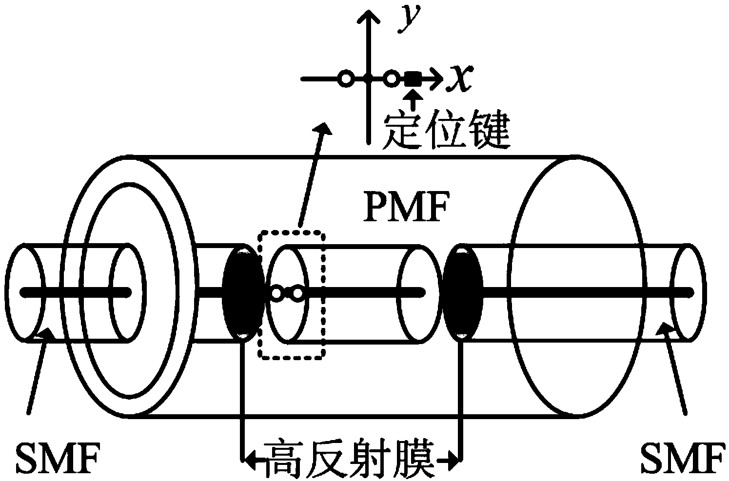
[0033] Such as figure 2 The schematic diagram of the internal structure of the optical fiber F-P interferometer is shown. The optical fiber F-P interferometer is composed of two single-mode optical fibers SMF at the beginning and the end and a polarization-maintaining optical fiber PMF in the middle. The two ports of the SMF close to the polarization-maintaining optical fiber PMF are coated with high reflection coating . When the light is incident on the fiber optic F-P interferometer, it will produce multi-beam interference between two high reflection films. Hypothesis E 0 is the complex amplitude of the incident photoelectric vector, their incidence angle in the high reflection film is d, the distance between the hig...
PUM
Abstract
The invention discloses a laser frequency shift detecting method and device with a dual-cavity F-P interferometer which is formed on the basis of polarization maintaining optical fibers. The device comprises a laser device, an acoustic optical modulator (AOM), an erbium-doped optical fiber amplifier (EDFA), quarter-wave plates, a collimator, a telescope, a first polarization maintaining optical fiber, a first circulator, a first narrow-band fiber bragg grating (FBG), a polarization controller (PC), an optical fiber F-P interferometer, an F-P interferometer controller, a polarization beam splitter (PBS), a first single photon counting module (SPCM), a second SPCM, a second polarization maintaining optical fiber, a second circulator, a second narrow-band FBG, a third SPCM and an acquisition card. According to the laser frequency shift detecting method and device with the dual-cavity F-P interferometer which is formed on the basis of the polarization maintaining optical fibers, a laser radar fiber integrated single-emission double-receiving light path is developed, two receiving optical fibers are spliced in the same cladding to form a dual D involution optical fiber, separation of energy detection and frequency shift detection is achieved, the signal to noise ratio of the frequency shift detection is increased, a dual-edge detection technology can be successfully achieved only by the single-channel F-P interferometer, the energy utilization ratio is high, and the method is simple.
Description
technical field [0001] The invention belongs to the technical field of optical detection, and in particular relates to a laser frequency shift detection method and equipment based on a polarization-maintaining optical fiber forming a double-cavity F-P interferometer. Background technique [0002] Since the 1980s, the direct detection wind lidar technology has gradually matured, and the direct detection radar technology has emerged in the field of wind detection lidar with its unique advantages, such as high time resolution and high spatial resolution. Basic research on Doppler direct detection wind lidar based on F-P interferometer has been carried out at home and abroad, including system parameter design, simulation and other work, foreign countries such as: OHP Observatory in France; ALAMOR jointly developed by Germany, Britain, Norway, etc. Systems; GLOW and Groundwinds systems developed by NASA, Natl Ctl Atmospher Res, and Michigan Aerospace Corporation of the United Sta...
Claims
Application Information
Patent Timeline
Application Date:The date an application was filed.
Publication Date:The date a patent or application was officially published.
First Publication Date:The earliest publication date of a patent with the same application number.
Issue Date:Publication date of the patent grant document.
PCT Entry Date:The Entry date of PCT National Phase.
Estimated Expiry Date:The statutory expiry date of a patent right according to the Patent Law, and it is the longest term of protection that the patent right can achieve without the termination of the patent right due to other reasons(Term extension factor has been taken into account ).
Invalid Date:Actual expiry date is based on effective date or publication date of legal transaction data of invalid patent.