Channel detection method and device in large-scale antenna system

A technology of transmitting antenna and virtual channel, applied in the field of multi-user multi-input multi-output transmission technology, can solve problems such as difficulty in pilot pattern

Active Publication Date: 2019-02-12
ALCATEL LUCENT SHANGHAI BELL CO LTD
View PDF3 Cites 0 Cited by
  • Summary
  • Abstract
  • Description
  • Claims
  • Application Information

AI Technical Summary

Problems solved by technology

Large-scale antenna systems may use more than 100 antennas in the base station, an

Method used


Image

  • Channel detection method and device in large-scale antenna system
  • Channel detection method and device in large-scale antenna system
  • Channel detection method and device in large-scale antenna system

Examples


Embodiment Construction

[0022] The detailed description of the drawings is intended as a description of presently preferred embodiments of the invention and is not intended to represent the only forms in which the invention can be embodied. It is to be understood that the same or equivalent function may be performed by different embodiments, which are intended to be encompassed within the spirit and scope of the invention.

[0023] Those skilled in the art will understand that the means and functions described herein can be implemented using software functions in combination with a programmed microprocessor and a general-purpose computer, and / or implemented using an application-specific integrated circuit (ASIC). It should also be understood that although the invention has been described primarily in terms of methods and apparatus, the invention may also be embodied as computer program products and systems comprising a computer processor and memory coupled to the processor, wherein the memory is used ...


PUM


Abstract

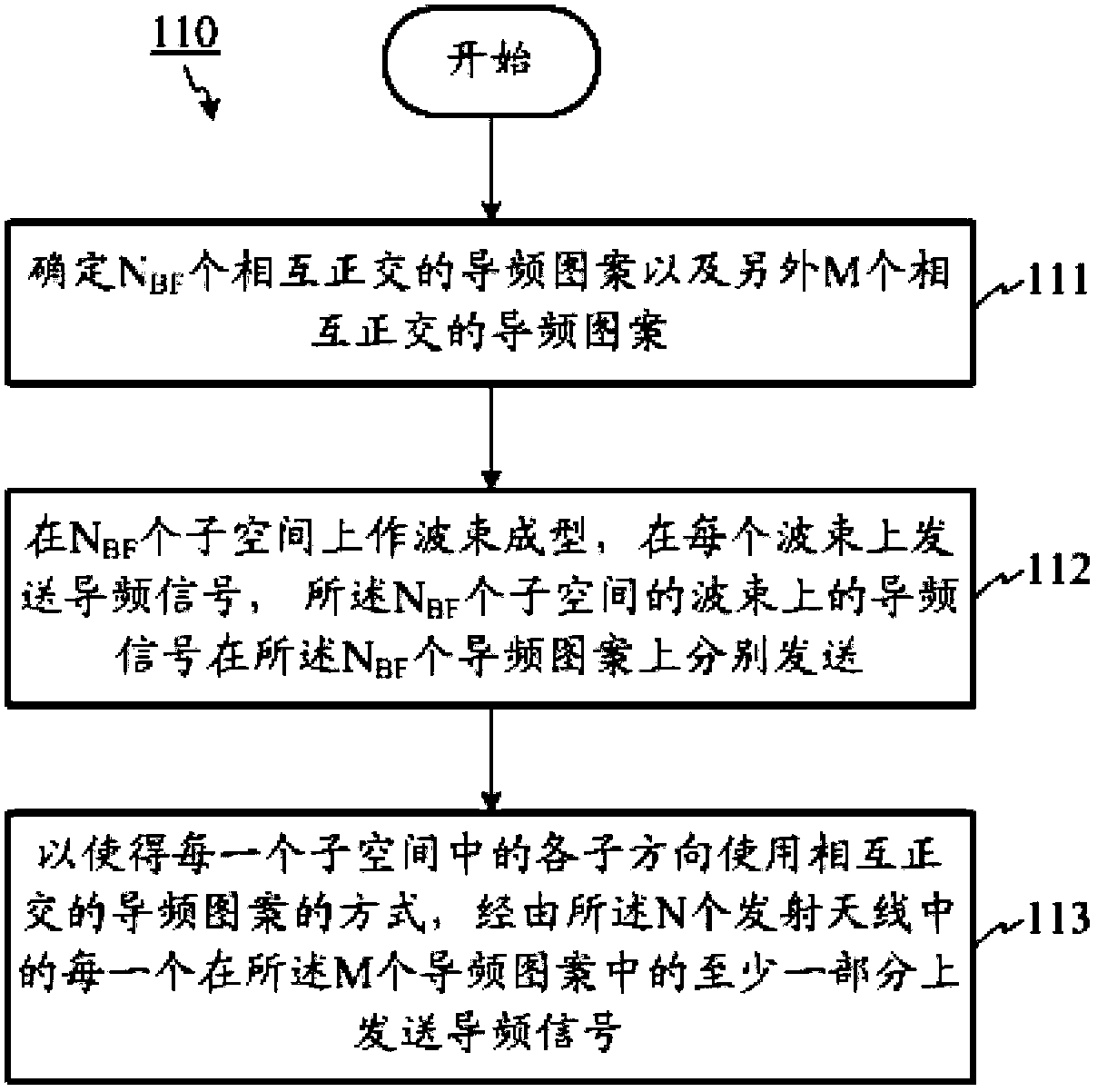
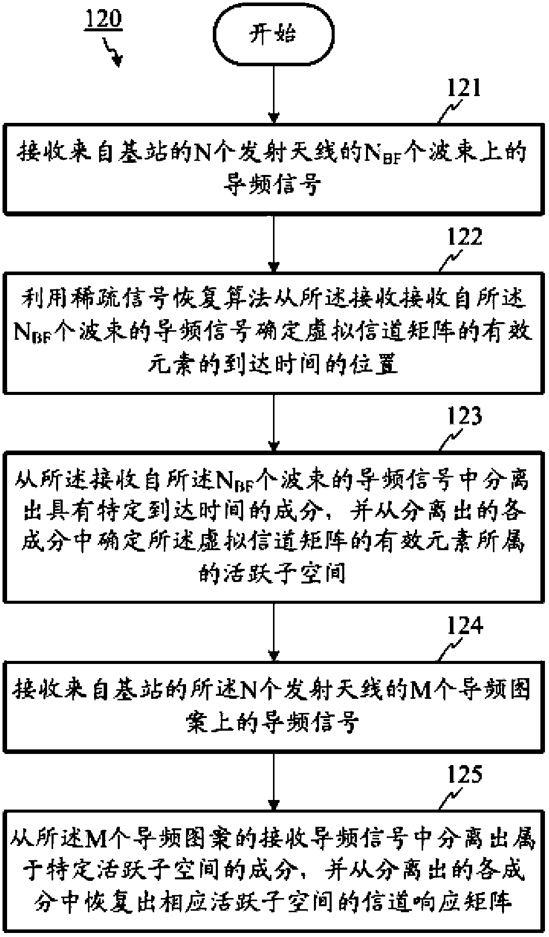
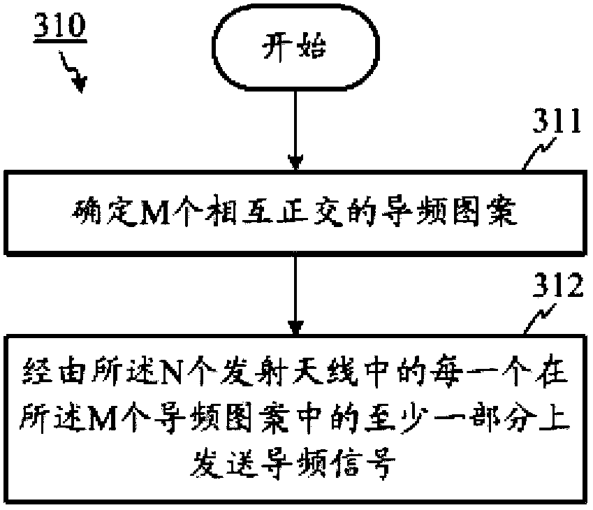
The present invention relates to a channel detection method and device in a system having a large number of antennas. In an embodiment, a method used in a base station having N transmitting antennas in a multiple input multiple output (MIMO) system is provided, which includes: determining NBF orthogonal pilot patterns and other M orthogonal pilot patterns; performing beamforming on NBF subspaces, and sending a pilot signal on each beam, where pilot signals on the beams of the NBF subspaces are sent respectively over the NBF pilot patterns; and sending pilot signals over at least a part of the M pilot patterns through each of the N transmitting antennas, in a manner that sub-directions in each subspace use the orthogonal pilot patterns, where a value of NBF is 10%~15% of N, and a value of M is 15%~50% of N. By using channel sparsity of the system having a large number of antennas, pilot overhead is reduced, and at least equivalent system performance can be achieved.

Description

technical field [0001] The present invention generally relates to mobile communication technology, and more specifically, to a multiple user multiple input multiple output (Multiple User Multiple Input Multiple Output, MU MIMO) transmission technology. Background technique [0002] As the number of base station antennas increases, pilot overhead becomes an increasingly serious problem, especially for physical channel estimation in the downlink of frequency division duplex (FDD) systems, which usually require different antennas to use Orthogonal pilot patterns. Therefore, the pilot overhead increases linearly with the number of antennas, which severely weakens the capacity gain brought by more antennas. In a large-scale antenna system, more than 100 antennas may be used in a base station, and it is very difficult to assign mutually orthogonal pilot patterns to all antennas. Therefore, accurate downlink physical channel estimation and many subsequent downlink closed-loop MIM...

Claims


Application Information

Patent Timeline
IPC IPC(8): H04L1/06H04L27/26
CPCH04L5/0048H04B7/0413H04B7/0617H04L5/0023H04L5/0026H04L25/0204H04L25/022H04L25/0226H04L25/023H04L25/0256
Inventor 吴克颖
Owner ALCATEL LUCENT SHANGHAI BELL CO LTD
Why Eureka
Try Eureka