Feeding apparatus

A feeding device and material technology, applied in electrical components, electrical components and other directions, can solve the problems of low efficiency, unstable and reliable operation, low efficiency, etc., and achieve the effect of improving the efficiency of feeding

Active Publication Date: 2014-10-22
深圳市复德科技有限公司
View PDF4 Cites 9 Cited by
  • Summary
  • Abstract
  • Description
  • Claims
  • Application Information

AI Technical Summary

Problems solved by technology

Although the arrangement efficiency of the vibration plate is high, the efficiency of the entire processing process is greatly restricted due to the relatively low efficiency of the separation and feeding devices commonly used today, and high-efficiency production and processing cannot be achieved.
The commonly used separation and feeding devices are usually driven by the cylinder to block and separate the components. The separation and feeding device with this structure is not only inefficient, but also not stable and reliable enough.

Method used


Image

  • Feeding apparatus
  • Feeding apparatus

Examples


Embodiment Construction

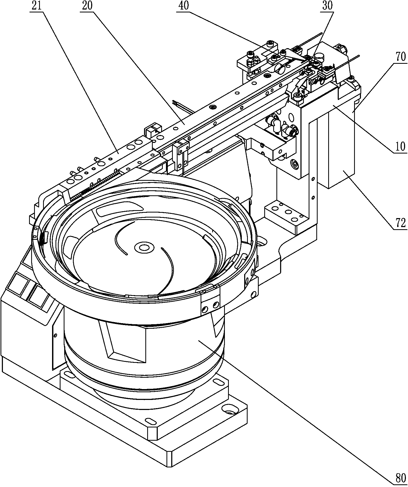
[0017] like figure 1 As shown, a feeding device includes a base 10, a flow channel 20 connected to the base 10, a material fixing mechanism 30 that is arranged at one end of the flow channel 20 and can move horizontally relative to the flow channel 20, and A stopper mechanism 40 for blocking the material in the flow channel 20 .

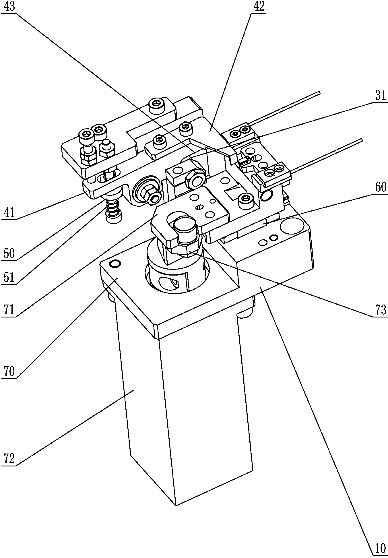
[0018] like figure 1 , 2 As shown, the material blocking mechanism 40 includes a swing block 41 and a blocking piece 42 connected with the swing block 41, the swing block 41 includes a guide surface 43, and the material fixing mechanism 30 includes a Cooperating rollers 31 . The guide surface 43 can be a certain inner surface of the guide channel provided on the swing block 41, or it can be a certain outer surface of the swing block 41, and the guide surface 43 can be a slope, a curved surface, or a slope and a slope. A combination of surfaces. In this embodiment, the guide surface 43 is an outer surface of the swing block 41 , and the guide sur...


PUM


Abstract

The invention discloses a feeding apparatus. The feeding apparatus comprises a pedestal, a channel connected with the pedestal, a material fixing mechanism which is arranged at one end of the channel and can horizontally move relative to the channel, and a material blocking mechanism which is used for blocking materials in the channel. The material blocking mechanism comprises a swing block and a blocking sheet connected with the swing block. The swing block comprises a guide surface. The material fixing mechanism further comprises a roller which is contacted with and cooperates with the guide surface. The feeding apparatus further comprises a vibration disc arranged at the other side of the channel. One side, which is close to the vibration disc, of the channel is provided with a magnet. The feeding apparatus with such a structure can rapidly separate the multiple materials which are tidily arranged in the channel and are closely attached and send the materials to a next processing station.

Description

technical field [0001] The invention relates to a feeding device, in particular to a feeding device capable of rapidly separating a plurality of materials that are close together in a flow channel and sending them to the next processing station. Background technique [0002] With the continuous development of technology, the efficiency of production, processing and assembly of electronic components is also getting higher and higher. For small components, it is usually necessary to arrange these components neatly through the vibrating plate and the flow channel connected to the vibrating plate, and then separate the components that are neatly arranged in the flow channel and close to each other and send them to on the corresponding processing station. Although the arrangement efficiency of the vibration plate is high, the efficiency of the entire processing process is greatly restricted due to the relatively low efficiency of the separation and feeding devices commonly used ...

Claims


Application Information

Patent Timeline
Patent Type & Authority Applications(China)
IPC IPC(8): H05K13/02
Inventor 龙超祥
Owner 深圳市复德科技有限公司
Why Eureka
Try Eureka