Vehicle body bottom structure

A car body and structure technology, applied in the field of car body substructure, can solve the problems of increased retreat, load transmission, and low bending rigidity crushing load of upper parts, so as to achieve the effect of increasing absorption and improving bending rigidity

Active Publication Date: 2014-10-22
HONDA MOTOR CO LTD
View PDF13 Cites 50 Cited by
  • Summary
  • Abstract
  • Description
  • Claims
  • Application Information

AI Technical Summary

Problems solved by technology

Therefore, as in the case of Patent Document 1, there are cases where the front mounting portion of the door provided on the front pillar moves rearward, making it difficult to open the door.
[0018] Moreover, in the vehicle body structure disclosed in Patent Document 2, only the instrument panel cross member and the gusset member are bonded, and the bonding force is weak, and once a collision load is applied to the side member in the event of a small-scale overlapping collision, for example, front end, the front end of the floor may be deformed and the amount of retreat of the lower member of the instrument panel toward the cabin side may increase.
[0019] In addition, in the invention described in Patent Document 3, since only one ridgeline portion is formed on the upper member, the bending rigidity of the upper member and the crushing load during a frontal collision are low relative to the load during a side collision. The problem
[0020] In addition, since the substantially horizontally formed portion of the lower member is vertically shifted relative to the floor, the load at the time of a side collision cannot be avoided and the load cannot be transmitted to the floor, resulting in a problem that the bending rigidity of the lower member is low.
[0021] Therefore, in the invention described in Patent Document 3, in order to increase the bending rigidity and crushing load of the side sill, a reinforcement member is separately provided between the side sill inner member and the side sill outer member (inside the side sill), but There will be a corresponding increase in the weight of the vehicle body
[0022] In addition, measures to increase the bending rigidity and crushing load of the side sill by increasing the plate thickness of the upper and lower members are also considered, but this will increase the weight of the vehicle body

Method used


Image

  • Vehicle body bottom structure
  • Vehicle body bottom structure
  • Vehicle body bottom structure

Examples


no. 1 approach >

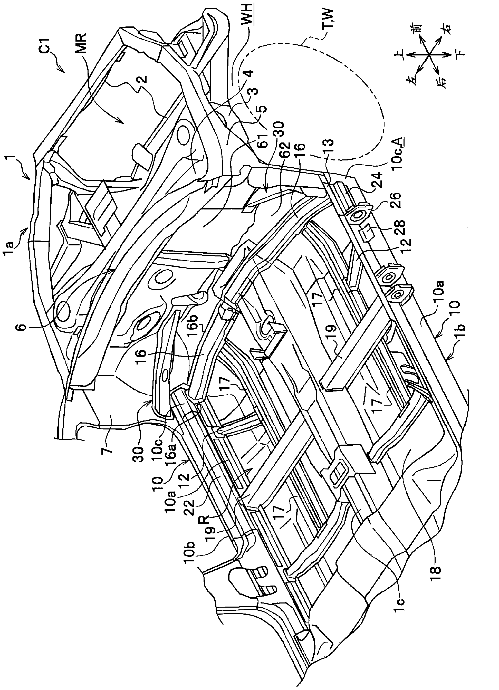
[0123] Regarding the embodiment of the present invention, refer to Figure 1 to Figure 9 Describe in detail. In the description, the same reference numerals are attached to the same elements, and overlapping descriptions are omitted. In addition, when describing a direction, it demonstrates based on front-back, left-right, up-and-down seen from the driver of a vehicle.

[0124] Such as figure 1 As shown, a vehicle C1 is constituted by an automobile having a power-mounted room MR and a front wheel room WH arranged in a vehicle body front portion 1a, and a vehicle room R arranged with a partition 6 between the power-mounted room MR and the front wheel room WH. The automobile includes, for example, automobiles of FR (front-engine, rear-wheel drive) type, FF (front-engine, front-wheel drive) type, four-wheel-drive type, and the like.

[0125] In addition, as the vehicle C1 to which the present invention is applied, only a pair of left and right front pillars 7 arranged on the le...

no. 2 approach >

[0163] Hereinafter, a second embodiment of the present invention will be described in detail with appropriate reference to the drawings. In addition, in each figure, "front and rear" and "up and down" indicated by arrows indicate the front and rear directions of the vehicle body and the up and down directions of the vehicle body, and "left and right" indicate the left and right directions (vehicle width direction) viewed from the driver's seat. In addition, in this embodiment, a vertical cross section means a vertical cross section.

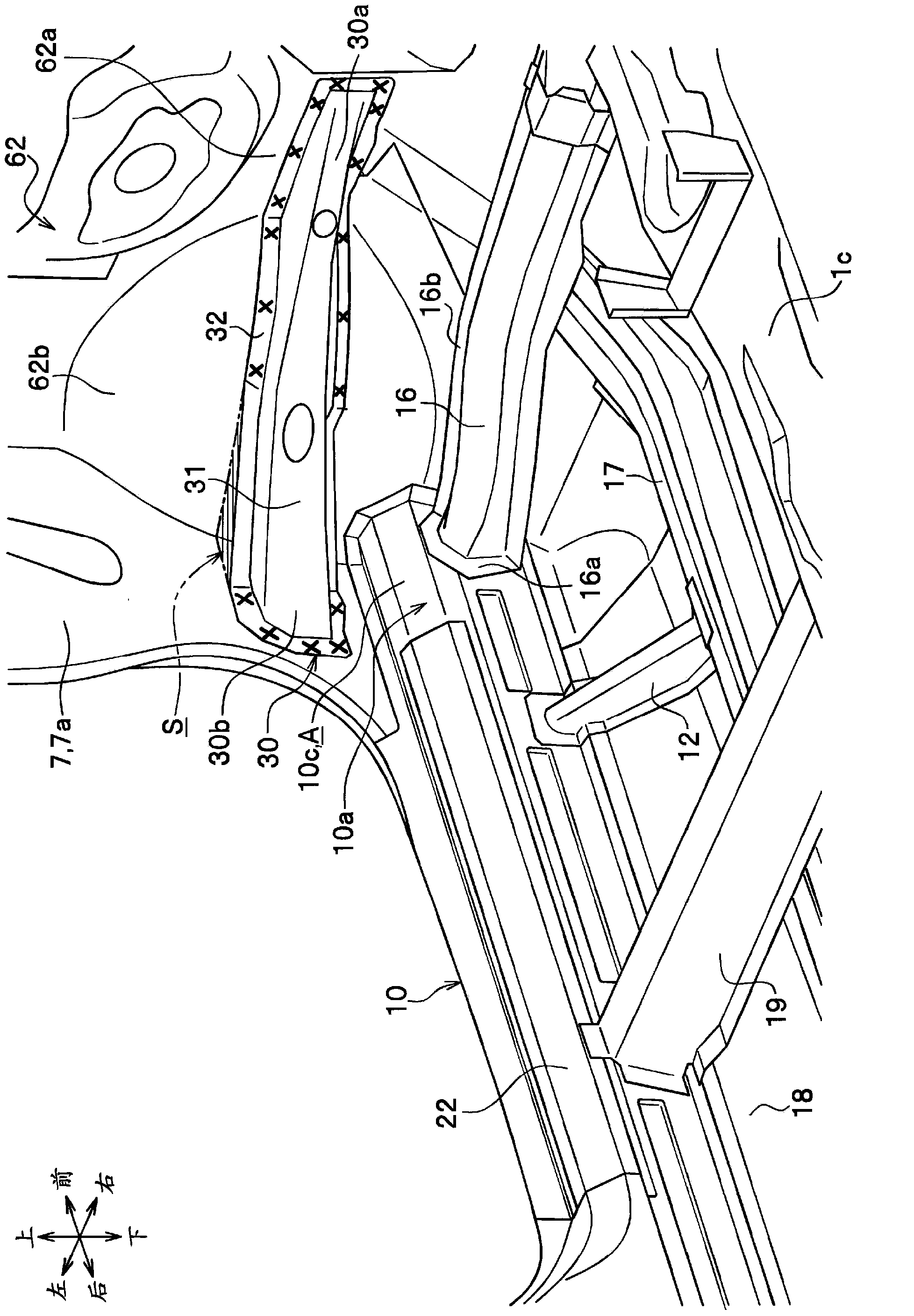
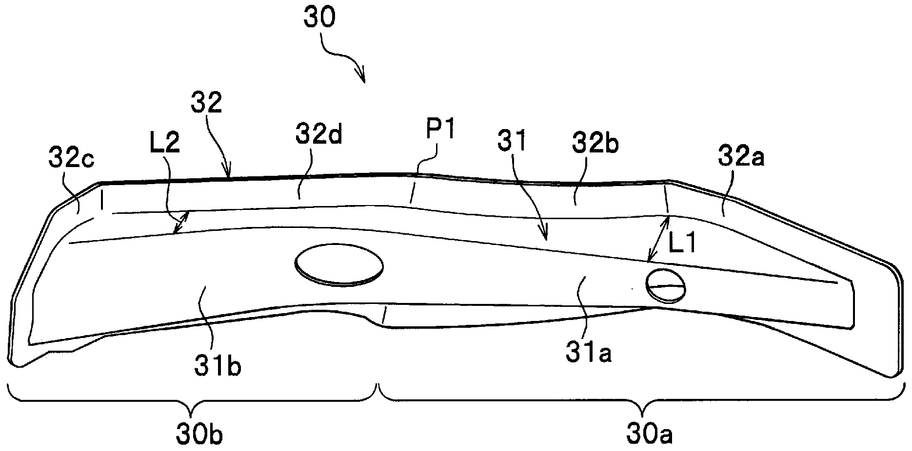
[0164] In addition, since the gusset plate 30 has the same structure as that of the first embodiment, detailed description thereof will be omitted.

[0165] Such as Figure 10 As shown, a vehicle C1 is constituted by an automobile having a power-mounted compartment MR disposed at the vehicle body front portion 1 a and a vehicle compartment R disposed across the partition 6 from the power-mounted compartment MR. The automobile includes, for exam...

no. 3 approach >

[0220] Hereinafter, a third embodiment of the present invention will be described in detail with appropriate reference to the drawings. In addition, in each figure, "front and rear" and "up and down" indicated by arrows indicate the front and rear directions of the vehicle body and the up and down directions of the vehicle body, and "left and right" indicate the left and right directions (vehicle width direction) viewed from the driver's seat. In addition, a longitudinal section means a vertical section.

[0221] In addition, since the gusset plate 30 has the same structure as that of the first embodiment, detailed description thereof will be omitted.

[0222] Such as Figure 20 As shown, a vehicle C1 is constituted by an automobile having a power-mounted compartment MR disposed at the vehicle body front portion 1 a and a vehicle compartment R disposed across the partition 6 from the power-mounted compartment MR. The automobile includes, for example, automobiles of FR (front...


PUM


Abstract

Provided is a vehicle body bottom structure whereby collision load absorption performance during a narrow offset crash can be improved and retraction of the A-pillar can be minimized. A vehicle body bottom structure comprising a dashboard lower (62) for partitioning a vehicle interior (R) and a power installation interior (MR) and also for partitioning the vehicle interior (R) and a wheel house (WH), an A-pillar (7) erected at the vehicle-widthwise end of the dashboard lower (62), and a gusset (30) spanning between the dashboard lower (62) and the A-pillar (7); the gusset (30) being designed such that one end side is bonded to the dashboard lower (62) and grows farther from the dashboard lower (62) the nearer to the A-pillar (7), the other end side is bonded to the A-pillar (7), and a collapse space (S) having a substantially triangular shape in a plan view is formed in the portion enclosed by the dashboard lower (62), the A-pillar (7), and the gusset (30).

Description

technical field [0001] The present invention relates to an underbody structure of a vehicle body, and in particular to an underbody structure capable of improving the absorbability of a collision load in a small-area overlap-offset collision. The right side or the left side is shifted, and the hard structure such as the front side frame of the collision object such as the oncoming vehicle collides with the front part of the wheel well of the vehicle body, such that it collides in a slightly brushed state. Background technique [0002] For example, Patent Document 1 discloses a vehicle body structure capable of suppressing deformation of the vehicle body by dispersing the collision load and increasing the strength of the vehicle body when the vehicle collides with a collision object such as an oncoming vehicle. [0003] Figure 33 It is a schematic plan view of a vehicle body showing a state where a collision load is received in a small-scale overlapping offset collision of t...

Claims


Application Information

Patent Timeline
Patent Type & Authority Applications(China)
IPC IPC(8): B62D25/20B62D25/14
CPCB62D25/16B62D25/082B62D25/14B62D25/025B62D21/152B62D25/2018B62D25/2036B62D25/20B62D21/155B62D25/145B62D25/081
Inventor 古崎雄也安井健山根昌晃
Owner HONDA MOTOR CO LTD
Why Eureka
Try Eureka