Transformer

A technology for transformers and secondary coils, applied in transformers, transformer/inductor magnetic cores, transformer/inductor components, etc., can solve problems such as mid-foot 4a breakage and mid-foot 4a damage, and achieve the effect of increasing leakage inductance

Inactive Publication Date: 2014-10-22
FDK CORP
View PDF6 Cites 7 Cited by
  • Summary
  • Abstract
  • Description
  • Claims
  • Application Information

AI Technical Summary

Problems solved by technology

[0007] Therefore, although it is conceivable that only the above-mentioned midfoot 4a is thinned to cope with the method to solve the above-mentioned problem, first of all, it is difficult to process only the midfoot 4a thinly, and there is also a possibility that the midfoot 4a breaks during assembly, Or after being installed in the power circuit for use, for example, there is a risk of damage to the midfoot 4a at an unexpected position due to vibration, etc.

Method used


Image

  • Transformer
  • Transformer
  • Transformer

Examples


no. 1 approach

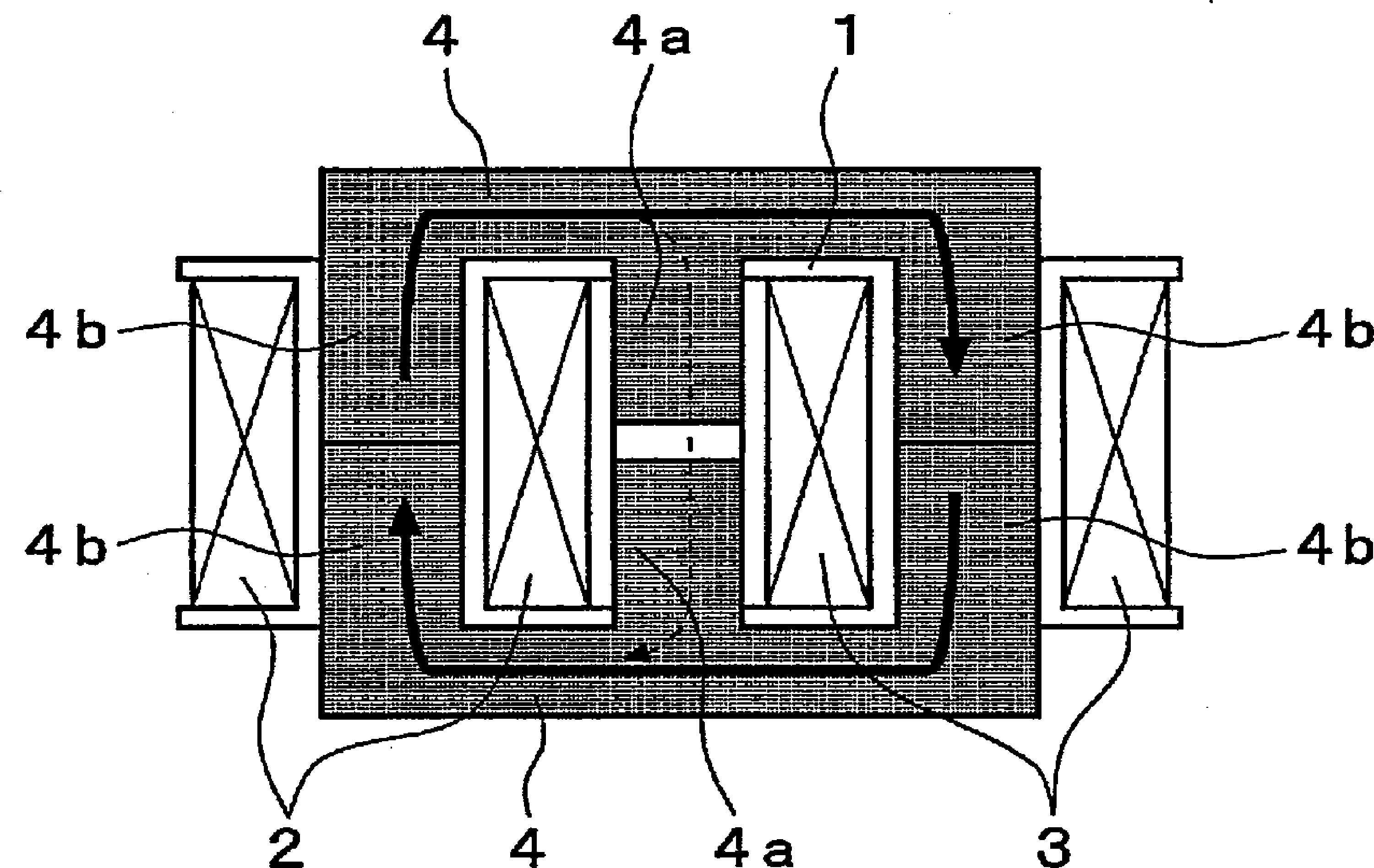
[0041] Figure 1 ~ Figure 3 It is a figure which shows the 1st Embodiment of the transformer concerning this invention, Figure 4 ~ Figure 6B Each is a figure which shows the modification.

[0042] exist Figure 1 ~ Figure 3 In , the symbol 10 is the primary coil wound on the bobbin 11 , and the symbol 12 is the secondary coil wound on the bobbin 13 . In addition, these primary coils 10 and secondary coils 12 are arranged so that their axes coincide with each other by stacking the end faces of the respective ring-shaped bobbins 11 and 13 . In addition, reference numerals 10 a and 12 a are lead wires of the primary coil 10 and the secondary coil 12 , respectively.

[0043] Furthermore, these primary coils 10 and secondary coils 12 are arranged with figure 1 The core that forms the ring-shaped main closed magnetic circuit shown by the solid arrow in .

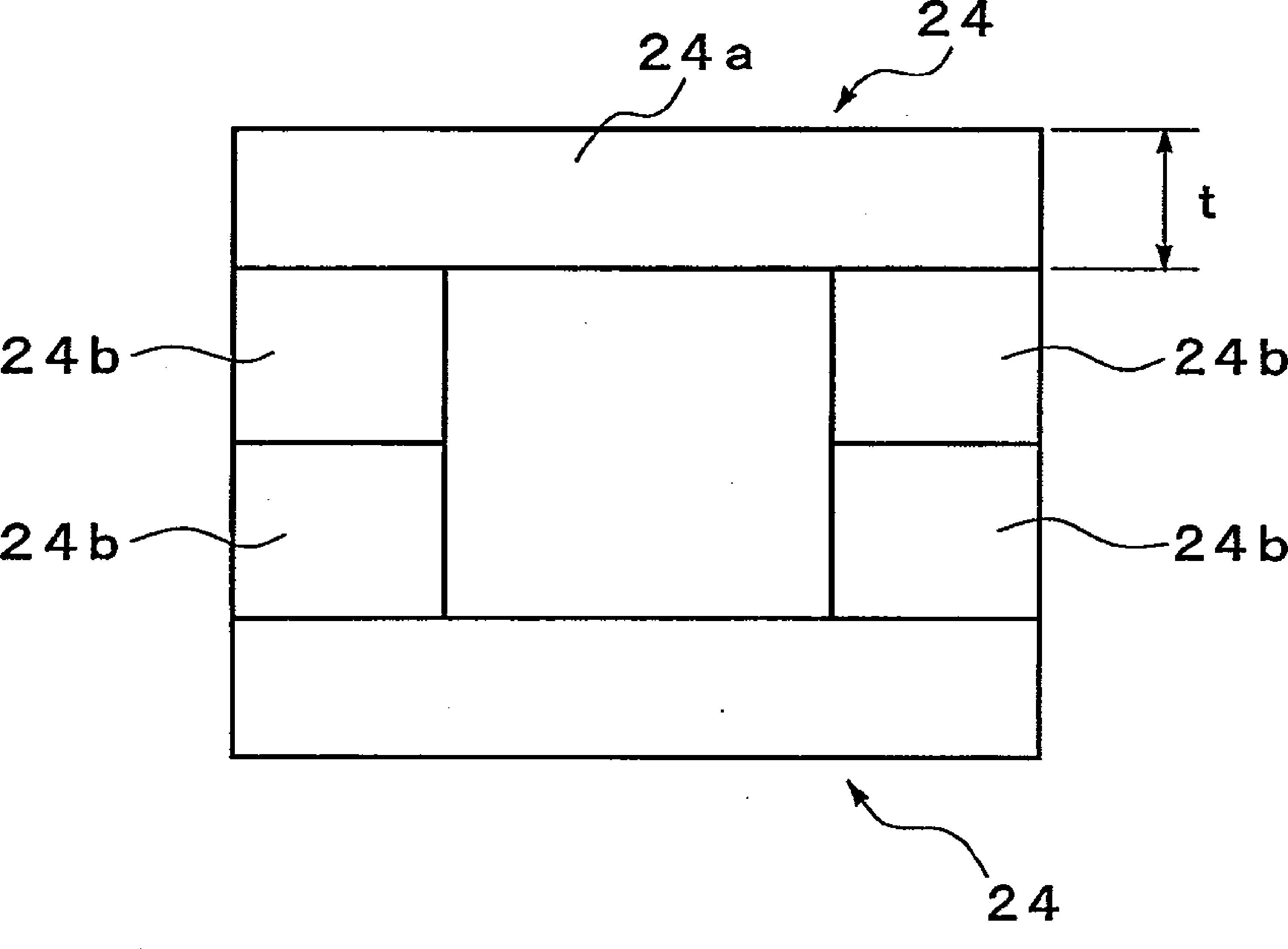
[0044] The core is formed of a pair of E-type ferrite cores (hereinafter, simply referred to as E-type cores) 14 arranged...

no. 2 approach

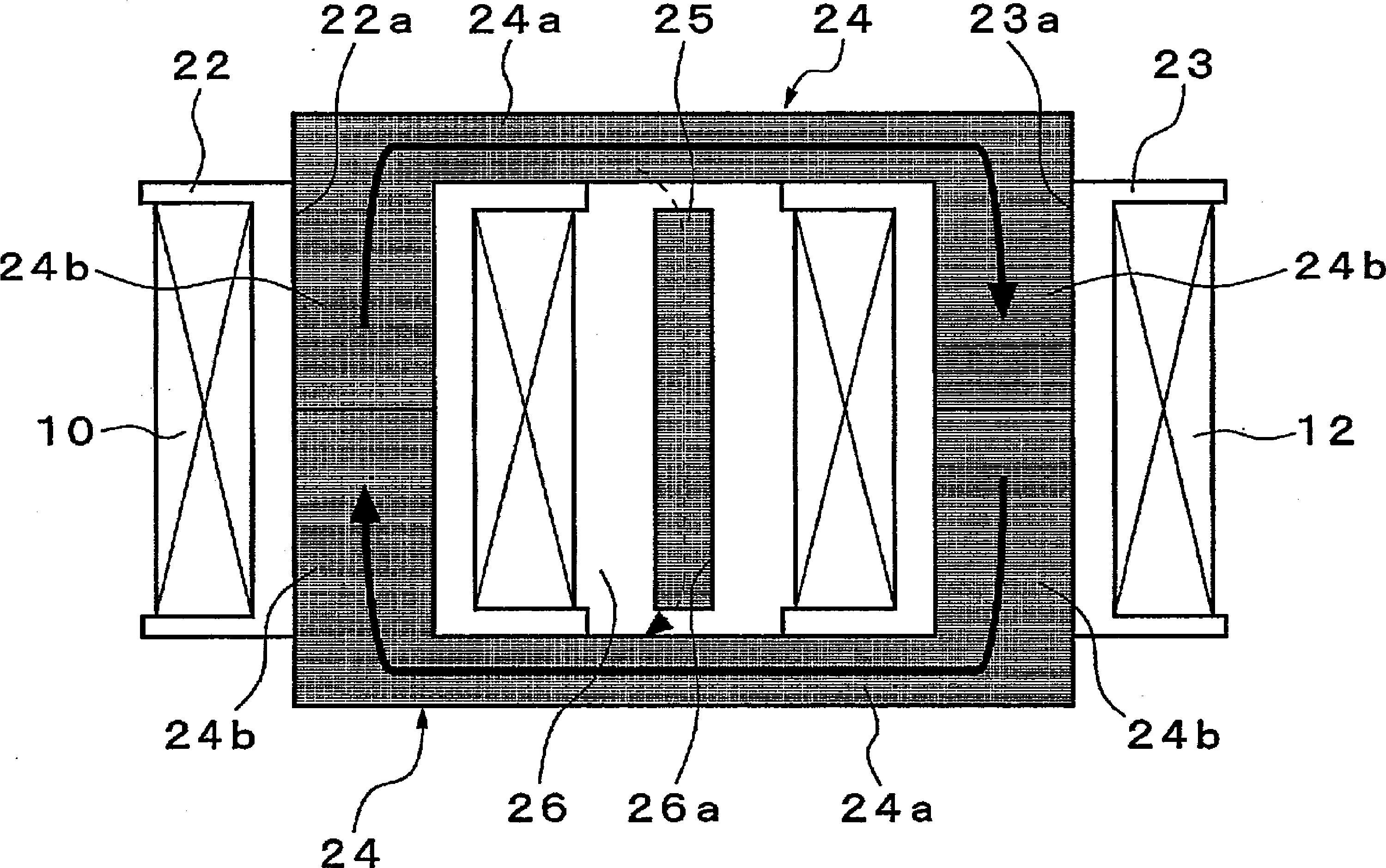
[0055] Figure 7 ~ Figure 10 It is a figure which shows 2nd Embodiment of the transformer concerning this invention.

[0056] In this transformer, the bobbin 22 around which the primary coil 10 is wound and the bobbin 23 around which the secondary coil 12 is wound are arranged with their axes parallel and with a gap formed between their outer peripheries. Here, the winding portions of the bobbin holders 22 and 23 are each formed in an elongated cylindrical shape in a cross section perpendicular to the axis, and both end portions are formed in an arc shape. As a result, long holes 22a, 23a whose both end portions are arc-shaped are formed in the central portions of the bobbins 22, 23. As shown in FIG.

[0057] Furthermore, these primary coils 10 and secondary coils 12 are arranged with Figure 7 The core shown by the solid line arrow is used to form the main closed magnetic circuit in the shape of a word.

[0058] The core is a member formed in a square shape by a pair of U-...


PUM


Abstract

Provided is a transformer for which leak inductance can be adjusted as desired and machining is simple, it being possible to significantly reduce the size of the transformer. A transformer provided with a primary coil (10), a secondary coil (12), and a core (14) forming a ring-shaped closed magnetic circuit by being disposed between the primary coil and the secondary coil, wherein a magnetic body (15) having a sectional area smaller than the sectional area of the core is disposed between the primary coil (10) and the secondary coil (12) such that a shortcut in the ring-shaped closed magnetic circuit is formed across a gap between both ends of the magnetic body (15) and the core.

Description

technical field [0001] The present invention relates to a transformer incorporated in a power supply circuit, and more specifically, to a transformer in which leakage inductance is increased and miniaturized. Background technique [0002] As a transformer incorporated in a power supply circuit, a transformer that increases leakage inductance by positively generating magnetic force leakage transmitted from a primary coil to a secondary coil is known. [0003] Figure 11 In a conventional transformer of this type, the primary coil 2 is wound on one end side of the bobbin 1, the secondary coil 3 is wound on the other end, and the middle legs 4a of each other are inserted into the bobbin, and the outer legs 4b are along the A pair of E-shaped cores 4 arranged opposite to each other on the outer peripheries of the primary coil 2 or the secondary coil 3 form a closed magnetic circuit. [0004] In order to increase the leakage inductance in the transformer having the above configu...

Claims


Application Information

Patent Timeline
Patent Type & Authority Applications(China)
IPC IPC(8): H01F38/08
CPCH01F38/08H01F3/14H01F27/24H01F27/28H01F27/346
Inventor 金子幸司大田智嗣
Owner FDK CORP
Why Eureka
Try Eureka