Vehicle heater and method for monitoring a vehicle

A vehicle heater and monitoring device technology, applied in vehicle components, ohmic resistance heating, heating/cooling equipment, etc., can solve problems such as reducing output

Active Publication Date: 2014-10-22
WEBASTO AG
View PDF4 Cites 5 Cited by
  • Summary
  • Abstract
  • Description
  • Claims
  • Application Information

AI Technical Summary

Problems solved by technology

If a permanent failure occurs in such a vehicle heater, it must be assumed that this permanent failure will also...

Method used


Image

  • Vehicle heater and method for monitoring a vehicle
  • Vehicle heater and method for monitoring a vehicle
  • Vehicle heater and method for monitoring a vehicle

Examples


Embodiment Construction

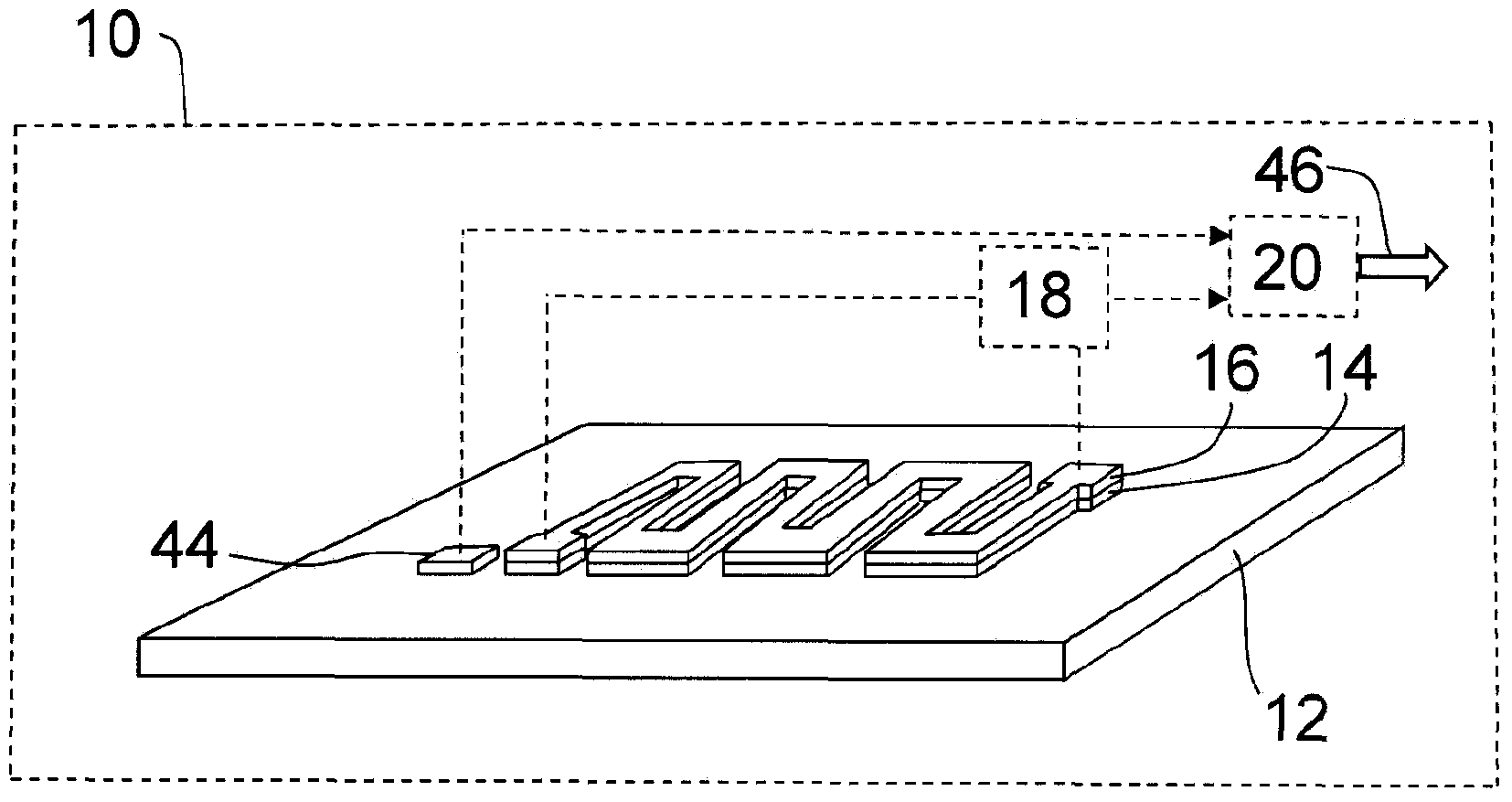
[0028] figure 1 A schematic partial perspective view of a first exemplary embodiment of a vehicle heater 10 is shown and at the same time it illustrates the monitoring method.

[0029] figure 1 The vehicle heater 10 shown in and all other vehicle heaters described below may be, for example (and not limited thereto), both air heaters or so-called water heaters for electric or hybrid vehicles. Air heaters differ from so-called water heaters in that in an air heater the air flow to be heated is guided directly along the heat exchanger of the air heating device, whereas in a so-called water heater a liquid, usually water (hence the name) and an antifreeze liquid (such as glycol) is first directed through the water heater's heat exchanger, which directs the heat to the desired spot with the aid of a fluid and another heat exchanger.

[0030] all in figure 1 The vehicle heater 10 , shown only schematically as a box, comprises a main body 12 , which in this case is a heat exchange...


PUM


Abstract

A vehicle heater (10) has a main body (12) which supports a non-intrinsically safe heat conductor layer (14), and a temperature monitoring device (16, 18, 20, 44) assigned to the heat conductor layer (14). The temperature monitoring device (16, 18, 20, 44) is designed to distinguish and report at least the three following states: normal operation, reversible malfunction, and irreversible malfunction. Moreover, a method for monitoring a vehicle heater (10) is disclosed in which the following states are distinguished and reported: normal operation, reversible malfunction, and irreversible malfunction.

Description

technical field [0001] The invention relates to a vehicle heater, which includes a main body carrying a non-intrinsically safe heat conduction layer, and a temperature monitoring device is configured to the heat conduction layer. [0002] The invention also relates to a monitoring method for a vehicle heater. [0003] The body can in both cases be, for example, a heat exchanger, in particular a metal / air and / or metal / liquid heat exchanger. Background technique [0004] Compared with the intrinsically safe heat conduction layer (intrinsically safe heat conductor layer), such as PTC heat conduction layer, which can autonomously prevent excessive temperature rise by limiting the current, the non-intrinsically safe heat conduction layer here refers to the The case is not clear for all types of thermally conductive layers that have this ability to avoid unsafe states. [0005] Without being limited thereto, provision can be made, for example, to supply the non-intrinsically saf...

Claims


Application Information

Patent Timeline
IPC IPC(8): H05B1/02H05B3/26B60H1/22G05D23/24
CPCH05B3/262H05B2203/003H05B1/0236H05B2203/023H05B2203/013B60H1/2218
Inventor D·比特策克T·卡贝利茨K·格特D·埃克特F·韦格纳H·雷西贝格尔U·赖因霍尔茨
Owner WEBASTO AG
Why Eureka
Try Eureka