Drum type natural gas drying device

A drying device and natural gas technology, applied in the direction of gas fuel, petroleum industry, dispersed particle separation, etc., can solve the problems of adsorbent failure, high frequency of adsorbent replacement, short use time, etc., to reduce the amount of water vapor and improve drying effect, the effect of accelerating the discharge speed

Inactive Publication Date: 2016-05-11
随州中燃城市燃气发展有限公司
View PDF6 Cites 1 Cited by
  • Summary
  • Abstract
  • Description
  • Claims
  • Application Information

AI Technical Summary

Problems solved by technology

However, when the water vapor content in natural gas is high, the adsorbent will fail in a short time, resulting in a short service life of the existing natural gas dryer and a high frequency of adsorbent replacement

Method used


Image

  • Drum type natural gas drying device
  • Drum type natural gas drying device

Examples


Embodiment 1

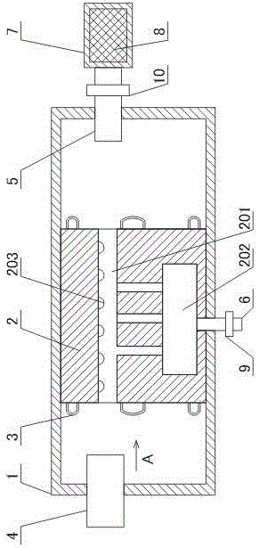
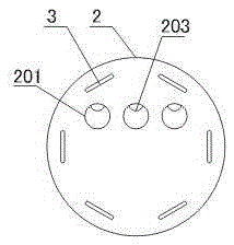
[0026] Such as figure 1 and figure 2 As shown, the cylindrical natural gas drying device includes a drying chamber 1, a condensation column 2, a condensation pipe 3, an air inlet pipe 4, an air outlet pipe 5, a liquid outlet pipe 6, a drying pipe 7, and an adsorbent 8; the condensation column 2 is set with the drying chamber In 1, the condensation pipe 3 reciprocates through the condensation column 2 in the circumferential direction of the condensation column 2. A plurality of horizontal flow channels 201 are opened on the condensation column 2, and a liquid collection cavity 202 is opened at the lower part of the condensation column 2. The liquid collection cavity 202 is located at Below the horizontal flow channel 201, the liquid collection cavity 202 communicates with each horizontal flow channel 201; the air inlet pipe 4 is arranged on the left side of the drying chamber 1, the air outlet pipe 5 is arranged on the right side of the drying chamber 1, and the liquid outlet ...

Embodiment 2

[0030] Such as figure 1 As shown, on the basis of Embodiment 1, this embodiment further includes a second shut-off valve 10 disposed on the air outlet pipe 5 .

[0031] The second stop valve 10 is provided, and when the natural gas is not dried, the second stop valve 10 is closed to prevent the condensed water in the liquid collection cavity 202 from evaporating and entering the drying pipe 1, further improving the service life of the adsorbent 9.

Embodiment 3

[0033] Such as figure 1 As shown, in this embodiment, on the basis of Embodiment 1 or 2, a plurality of hemispherical protrusions 203 are provided on the upper inner surface of the horizontal flow channel 201 .

[0034] The condensed water located on the upper part of the inner surface of the horizontal flow channel can collect along the outer surface of the hemispherical protrusion 203, and finally gather into droplets at the lowest point of the hemispherical protrusion 203 and fall down. Compared with the condensed water flowing downward along the inner surface of the horizontal flow channel, Its condensate drains faster.


PUM


Abstract

The invention discloses a cylindrical natural gas drying device. The device comprises a drying cavity, a condensation column, a condensation pipe, a gas inlet pipe, a gas outlet pipe, a liquid outlet pipe, a drying pipe and adsorbents, wherein the condensation column is arranged in the drying cavity; the condensation pipe penetrates through the condensation column back and forth in the peripheral direction of the condensation column; a plurality of horizontal runners are formed in the condensation column; a liquid collecting cavity is formed in the lower part of the condensation column, is arranged below the horizontal runners and is communicated with each horizontal runner; the gas inlet pipe is arranged on the left of the drying cavity; the gas outlet pipe is arranged on the right of the drying cavity; the liquid outlet pipe is communicated with the liquid collecting cavity; perforated plates are arranged at the two ends of the drying pipe; the adsorbents are arranged in the drying pipe; the drying pipe is communicated with the gas outlet pipe. The device is suitable for natural gases with high water vapor contents and can prevent the adsorbents from losing effects in a short time and improve the natural gas drying effects.

Description

technical field [0001] The invention relates to the field of gas treatment, in particular to a cylinder type natural gas drying device. Background technique [0002] Natural gas is usually mixed with a small amount of water vapor, which affects the combustion of natural gas. Therefore, before the natural gas is combusted, the water vapor contained in the natural gas needs to be removed. [0003] At present, in order to remove the water vapor in the natural gas, the water vapor in the natural gas is mainly adsorbed by a drier containing an adsorbent. For example, the Chinese patent application with publication number "201959708U" discloses a portable natural gas dryer. This type of dryer uses an adsorbent in it to adsorb water vapor. However, when the water vapor content in natural gas is high, the adsorbent will fail in a short time, resulting in a short service life of the existing natural gas dryer and a high frequency of adsorbent replacement. Contents of the inventi...

Claims


Application Information

Patent Timeline
Patent Type & Authority Patents(China)
IPC IPC(8): B01D53/26C10L3/10
Inventor 吕忠贵
Owner 随州中燃城市燃气发展有限公司
Why Eureka
Try Eureka