
a shearing machine

A technology of plate shears and cutting tools, which is applied in the field of plate processing, can solve the problems of waste of resources, waste of raw materials, uneven surface of the plate body, etc., and achieve the effect of convenient adjustment

Inactive Publication Date: 2016-05-11
广州市神钢机床有限公司
View PDF6 Cites 0 Cited by
  • Summary
  • Abstract
  • Description
  • Claims
  • Application Information

AI Technical Summary

Problems solved by technology

However, before the plate body is sent to the shearing machine after leveling, it is prone to collision during storage or transportation, and the bending will cause the surface of the plate body to be uneven.
Therefore, when the plate is cut, when the end of the plate touches the stopper, the actual length of the plate is longer than the set cutting length due to the bending of the plate, so that the product size does not meet the requirements and wastes raw materials
Moreover, the conveying device currently used for conveying plates can only be applied to plates of the same thickness. However, due to the variety of thickness specifications of plate products, in order to facilitate the processing of plates of various thicknesses, it is often necessary to set up corresponding shears according to the thickness specifications of the plates. , which results in an increase in production costs and a waste of resources

Method used


Image

  • a shearing machine
  • a shearing machine

Examples


Embodiment 1

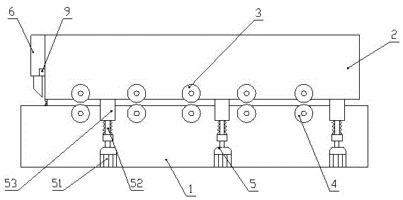
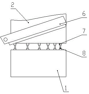
[0025] This embodiment provides a kind of shearing machine, such as figure 1 and figure 2 As shown, the shearing machine includes a lower support 1 , an upper support 2 , a pressing device arranged between the lower support 1 and the upper support 2 , and a cutting tool 6 . The lower roller assembly 4 is installed on the lower support 1, and the upper roller assembly 3 is installed under the upper support 2. The plate to be cut is placed between the lower roller assembly 4 and the upper roller assembly 3, and the upper roller assembly 3 and the lower roller assembly The rolling of assembly 4 drives the movement of the plate to be cut. Both sides of the lower support 1 are also provided with ejection devices 5, which are used to withstand the upper support 2 and adjust the height of the upper support 2 to change the distance between the upper roller assembly 3 and the lower roller assembly 4 , so as to adapt to plates of different thicknesses.

[0026] The pressing device c...


PUM


Abstract

The invention discloses a plate shearing machine, and relates to the technical field of plate machining. The plate shearing machine comprises an upper support, a lower support and an ejection device. The ejection device can eject the upper support and change the height of the upper support so as to change the distance between an upper idler wheel assembly and a lower idler wheel assembly, as a result, plates with different thicknesses can be positioned, and adjustment is convenient. A pressing device comprises a plurality of pressing pillars and a plurality of supporting pillars. As the plate on the side close to the rotary shaft end of a cutting tool is not prone to deformation in the cutting process and the plate close to the free end of the cutting tool is prone to deformation in the cutting process, the distance between adjacent supporting pillars decreases gradually from the side at the free end of the cutting tool to the side at the rotary shaft end of the cutting tool, and deformation of the plates can be effectively prevented in the cutting process.

Description

technical field [0001] The invention relates to the technical field of plate processing, in particular to a shearing machine. Background technique [0002] The shearing machine is an automatic processing equipment that precisely controls the processing size of the plate, performs automatic cycle shearing processing on large metal plates, and is transported to the next process by the feeding car. After shearing, the shearing machine should be able to ensure that the The straightness and parallelism requirements of the shearing surface of the material are met, and the distortion of the plate is minimized to obtain high-quality workpieces. However, when the shearing machine cuts narrow-edged workpieces, most of the cut workpieces are distorted, so it is necessary to increase the shaping process to ensure the quality of the workpieces. [0003] In addition, in the process of cutting the plate, the programmable controller is used to control the automatic shearing machine. The le...

Claims


Application Information

Patent Timeline
Patent Type & Authority Patents(China)
IPC IPC(8): B23D17/00B23D33/12B23D33/02
Inventor 王琬
Owner 广州市神钢机床有限公司
Learn More