Optical anti-counterfeiting element and valuable article of focusing micro-reflection element array

A technology for optical anti-counterfeiting and valuable items, applied in the security field, can solve the problems of loss of anti-counterfeiting function, low yield rate, and extremely high production precision requirements, and achieve the effects of facilitating observation, increasing yield rate, and large process tolerance

Active Publication Date: 2016-08-24
ZHONGCHAO SPECIAL SECURITY TECH +1
View PDF10 Cites 0 Cited by
  • Summary
  • Abstract
  • Description
  • Claims
  • Application Information

AI Technical Summary

Problems solved by technology

Since the window security thread only has adhesive glue on the back side, but no glue on the front side (the surface where the microlens array is located), the bond between the window security thread and the paper is poor, and it is easy to fall off during the circulation of banknotes
During the circulation of banknotes, pollution such as sweat stains and oil stains will change the optical characteristics of the microlens array, reducing its optical effect and losing its anti-counterfeiting function
The pattern magnification of the window security line is very sensitive to the period difference and angle between the lens array and the micro-pattern array, which requires extremely high manufacturing precision and low yield
In addition, due to the small period of the microlens array, the period of the micropattern array is also small, which limits the size of the microtext unit. The size limitation of the microtext unit directly determines the limited design of the micropattern structure.

Method used


Image

  • Optical anti-counterfeiting element and valuable article of focusing micro-reflection element array
  • Optical anti-counterfeiting element and valuable article of focusing micro-reflection element array
  • Optical anti-counterfeiting element and valuable article of focusing micro-reflection element array

Examples


Embodiment Construction

[0042] Specific embodiments of the present invention will be described in detail below in conjunction with the accompanying drawings. It should be understood that the specific embodiments described here are only used to illustrate and explain the present invention, and are not intended to limit the present invention.

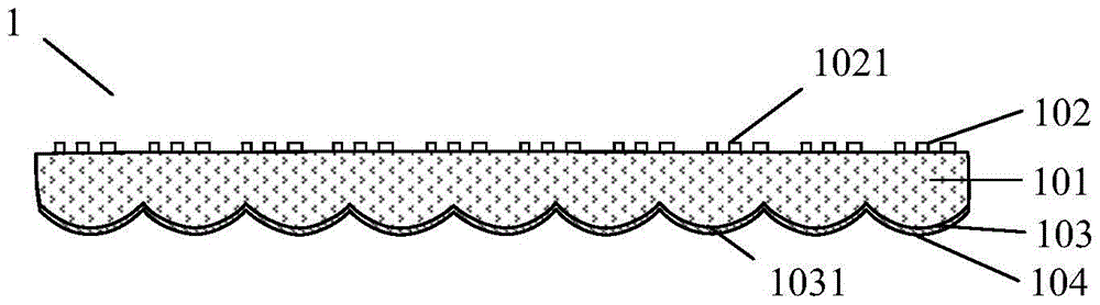
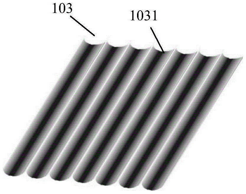
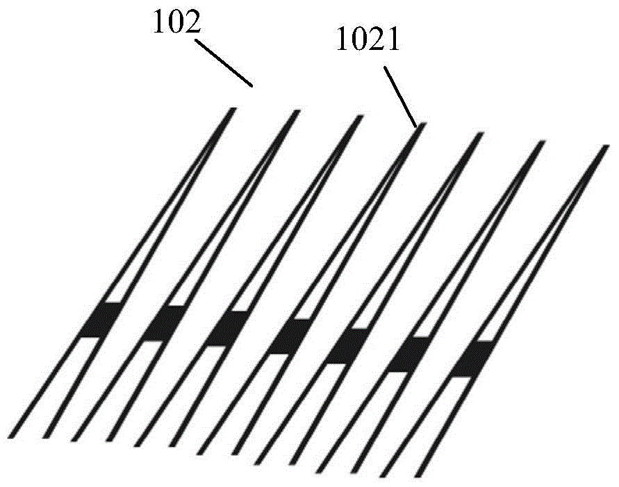
[0043] figure 1 A cross-sectional structure diagram of the optical anti-counterfeiting element provided by the present invention. Such as figure 1 As shown, the optical anti-counterfeiting element 1 includes a transparent base layer 101, a micropattern array 102 composed of micropattern units 1021 and a focusing microreflective element array 103 composed of focusing microreflective element units 1031. The micropattern array 102 is located on the first surface of the transparent base layer 101. The focusing micro-reflection element array 103 is located on the second surface of the transparent base layer 101 and covers at least a partial area of ​​the second sur...


PUM


Abstract

The invention discloses an optical anti-counterfeiting element of a focusing micro-reflection element array and a valuable article. The optical anti-counterfeiting element includes a transparent base layer, a micro-pattern array composed of micro-pattern units, and a focusing micro-reflection element array composed of focusing micro-reflection element units, the micro-pattern array at least partially covers the first surface of the transparent base layer, and the focusing micro-reflection element array is at least Partially covering the second surface of the transparent base layer, the distance between the micropattern unit and the focal plane of the focusing microreflective element unit is less than 50% of the focal length of the focusing microreflective element unit; the period t of the focusing microreflective element array L with the period of the micropattern array t w Satisfy And / or the included angle θ between the focusing micro-reflective element array and the micro-pattern array satisfies θ∈[‑5°, 5°]; wherein, n is a positive integer. The optical anti-counterfeiting element provided by the invention adopts a focusing micro-reflection element with a large diameter, has a large arrangement period, a large process tolerance, is relatively easy to manufacture, and can greatly increase the yield.

Description

technical field [0001] The invention relates to the security field, in particular to an optical anti-counterfeit element of a focusing micro-reflection element array and a valuable article. Background technique [0002] Optical anti-counterfeiting elements containing microlens arrays have been widely used in the field of anti-counterfeiting of valuable items, especially in banknotes. The structure of the optical anti-counterfeiting element containing the microlens array is that the microlens array is arranged on the upper surface of the transparent base layer, and the corresponding micropattern array is arranged on the lower surface of the transparent base layer. The micropattern array is located at or near the focal plane of the microlens array. The arrangement of the pattern array and the microlens array is roughly the same, and the Moiré magnification effect of the microlens array on the micropattern array is used to realize a pattern with a certain depth of field and a u...

Claims


Application Information

Patent Timeline
Patent Type & Authority Patents(China)
IPC IPC(8): B42D25/30B42D25/324G02B5/08
Inventor 朱军张宝利王晓利
Owner ZHONGCHAO SPECIAL SECURITY TECH
Why Eureka
Try Eureka