
Material sub-packaging machine

A technology of packing machine and materials, applied in packaging, solid materials, transportation and packaging, etc., can solve the problems of insufficient track width, power consumption, slow measurement and packaging, etc., achieving good buffering effect, saving energy and reducing power consumption Effect

Inactive Publication Date: 2014-10-29
CHENGFENG COMP EQUIP
View PDF1 Cites 3 Cited by
  • Summary
  • Abstract
  • Description
  • Claims
  • Application Information

AI Technical Summary

Problems solved by technology

Although the track can discharge materials of various shapes and special shapes into the weighing hopper, there are too many layers, and the vibrating bucket needs to rotate repeatedly for more circles to make the materials leak into the measuring hopper, and the width of the track is not wide enough. During the rotation of the vibrating bucket, it is easy to cause the material to fall, and the material needs to return to the track again, and the vibrating bucket needs to rotate repeatedly for more circles, which not only causes slow measurement and packaging, but also consumes more power
And for bulky materials, the vibrating plate can only hold a small amount of materials, which requires manual and continuous material addition, which is low in efficiency and high in cost

Method used


Image

  • Material sub-packaging machine
  • Material sub-packaging machine
  • Material sub-packaging machine

Examples


Embodiment Construction

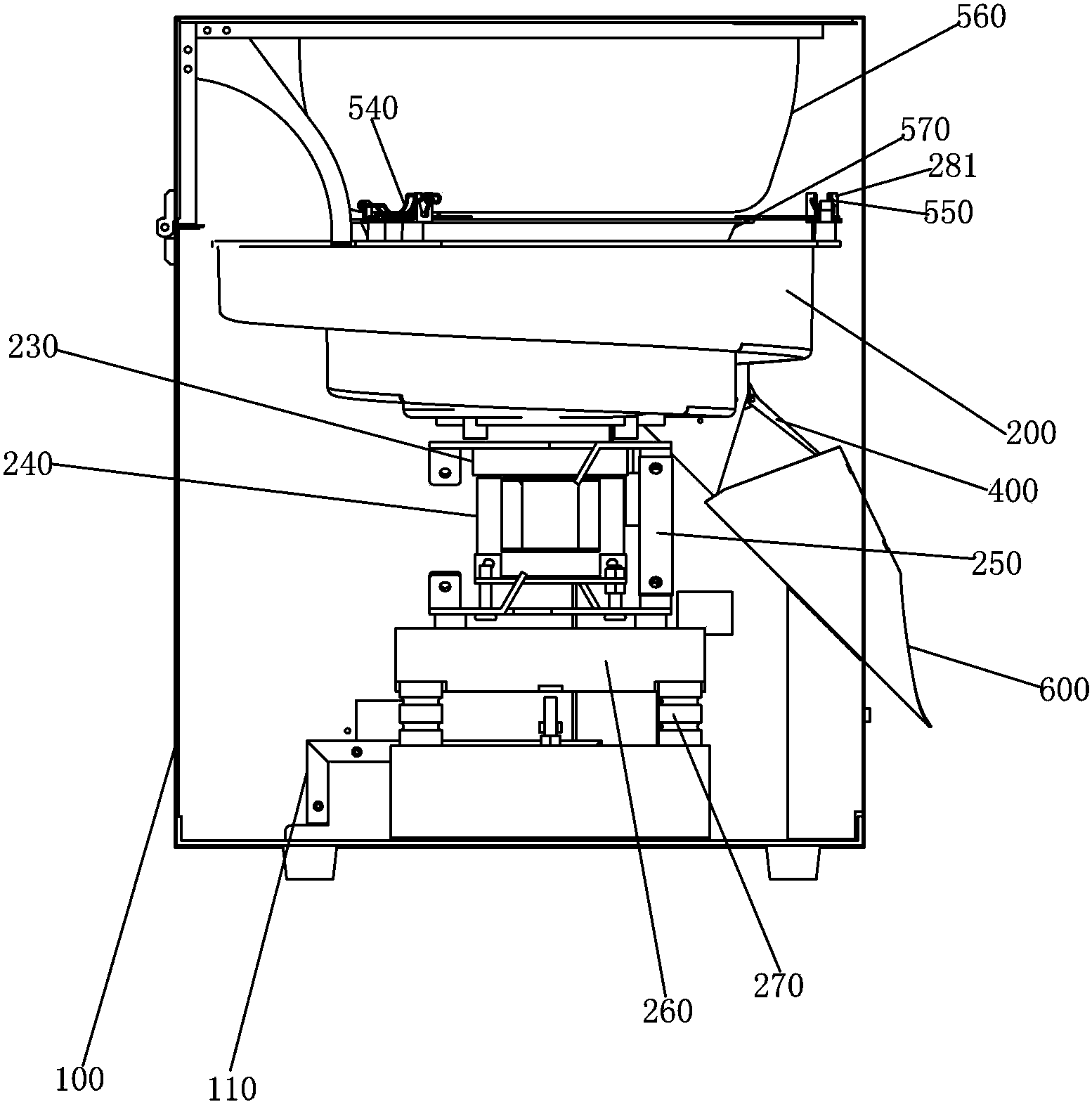
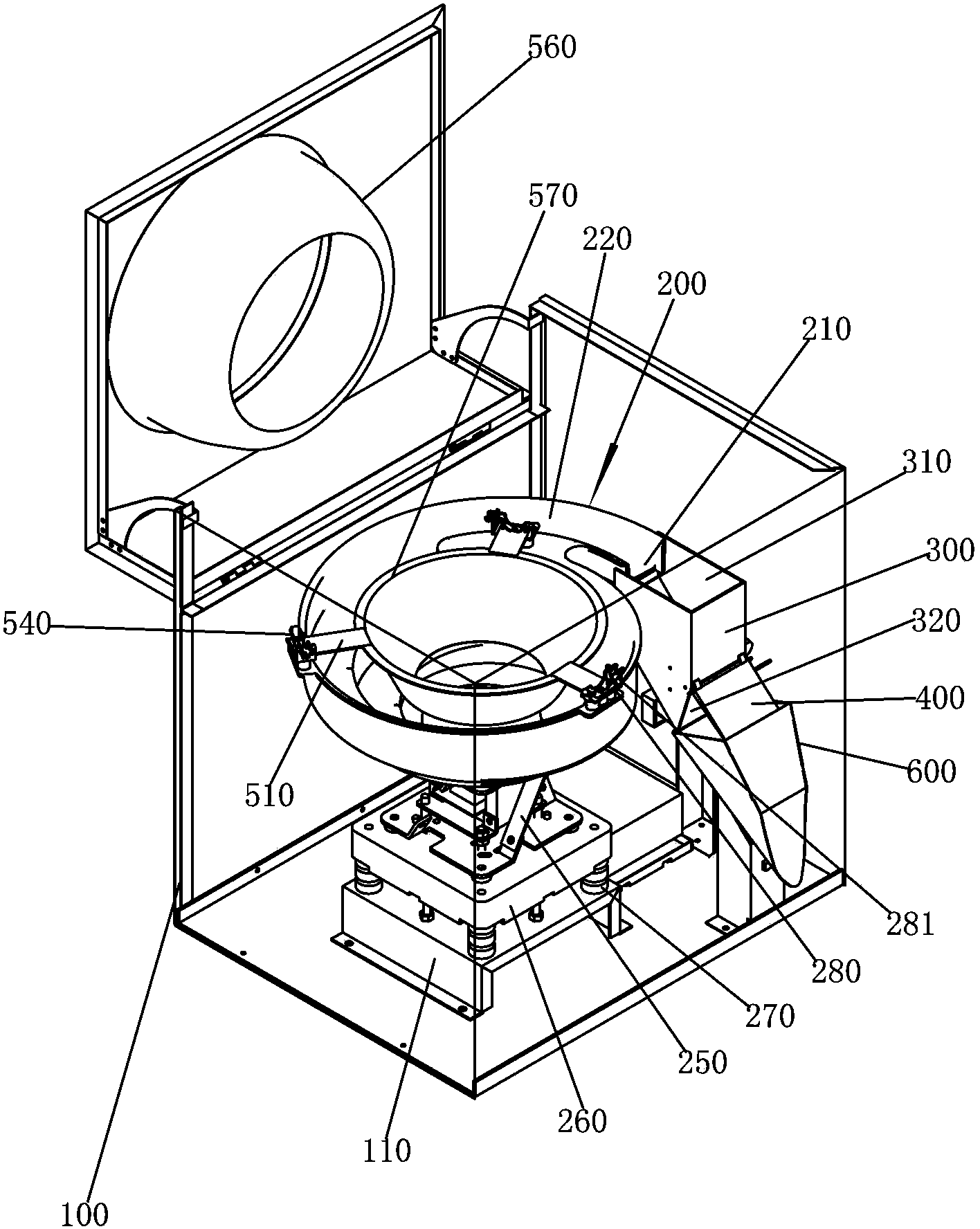
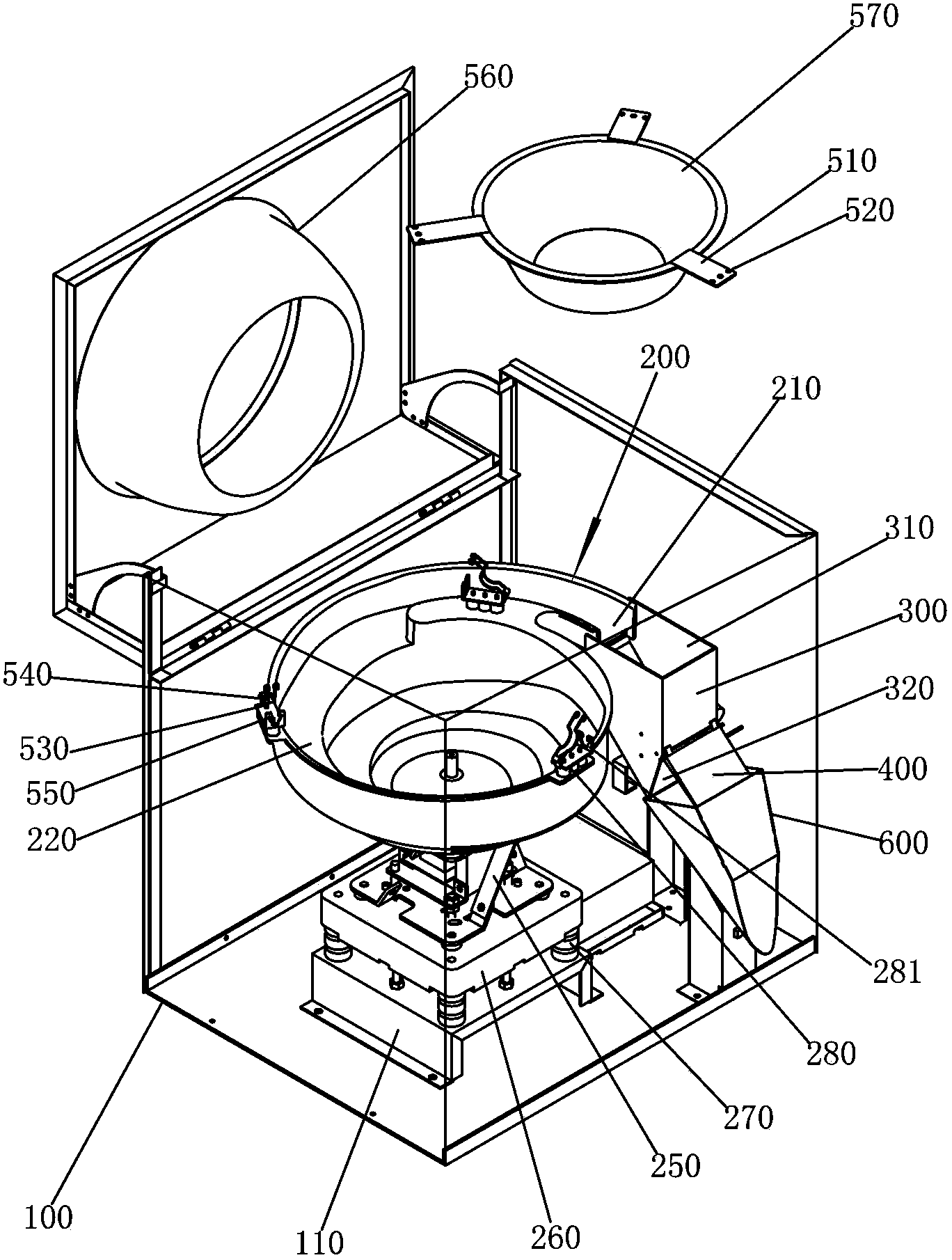
[0028] Please check Figure 1 to Figure 3 , a preferred embodiment of the material dispensing machine, the material dispensing machine, it includes a frame 100, a vibrating mechanism, a weighing mechanism, a baffle turning mechanism, a storage hopper and a buffer hopper 570.

[0029] A fixing base 110 is fixed inside the frame 100 . In this embodiment, the sidewall of the frame 100 is provided with a first opening and a second opening.

[0030] The vibrating mechanism can make the material rotate upwards. It is installed in the frame 100 and includes a vibrating drive unit and a vibrating plate 200 connected to the vibrating driving unit. The vibrating plate 200 is provided with a discharge port 210 .

[0031] In this embodiment, the vibrating plate 200 is provided with a track 220 , and the track 210 spirally rises along the inner wall of the vibrating plate 200 and extends from the bottom surface of the vibrating plate 200 to the outlet 210 . The length of the track is des...


PUM


Abstract

The invention discloses a material sub-packaging machine. The material sub-packaging machine comprises a rack, a vibrating mechanism, a weighing mechanism, a baffle turn-over mechanism, a material storage hopper and a buffering hopper. The vibrating mechanism is connected in the rack and comprises a vibration driving unit and a vibrating disk, and a discharging port is formed in the vibrating disk. The weighing mechanism is connected in the rack and comprises a weighing hopper with an inlet and an outlet, and the inlet of the weighing hopper corresponds to the discharging port. The baffle turn-over mechanism is connected in the rack and comprises a push-pull electromagnet and a baffle in transmission connection with the push-pull electromagnet, and the baffle is rotationally connected to the outlet of the weighing hopper. The material storage hopper is connected to the rack and located above the vibrating disk. The buffering hopper is detachably connected to the vibrating disk and located between the material storage hopper and the vibrating disk. More materials can be placed in the material storage hopper, because the buffering hopper is arranged, the material sub-packaging machine can be fully automatic, materials can be fed into the material storage hopper continuously, the trouble for attending the material storage hopper manually to prevent material accumulation is saved, and the production efficiency is greatly improved.

Description

technical field [0001] The invention relates to a material dispensing machine. Background technique [0002] China Patent Application No. 200920151324.X discloses an automatic metering machine. The vibrating bucket is in the shape of a disc. There is a slot on the side of the weighing bucket. The involute expands outward, and the movement direction of the material in the vibrating bucket is to move tangentially upward along the track and enter the weighing bucket. Although the track can discharge materials of various shapes and special shapes into the weighing hopper, there are too many layers, and the vibrating bucket needs to rotate repeatedly for more circles to make the materials leak into the measuring hopper, and the width of the track is not wide enough. During the rotation of the vibrating bucket, it is easy to cause the material to fall, and the material needs to return to the track again, and the vibrating bucket needs to rotate more times repeatedly, which not on...

Claims


Application Information

Patent Timeline
Patent Type & Authority Applications(China)
IPC IPC(8): B65B1/08B65B1/32
Inventor 林荣峰
Owner CHENGFENG COMP EQUIP
Learn More