
Heavy raw oil treatment apparatus, its application, and heavy raw oil treatment method

A treatment device and treatment method technology, which is applied in the treatment of hydrocarbon oil, hydroprocessing process, petroleum industry, etc., can solve the problems of wasting reactor space, etc., and achieve the effects of improved space utilization, fewer high-pressure valves, and reliable operating procedures

Active Publication Date: 2014-10-29
CHINA PETROLEUM & CHEM CORP +1
View PDF8 Cites 4 Cited by
  • Summary
  • Abstract
  • Description
  • Claims
  • Application Information

AI Technical Summary

Problems solved by technology

However, this method always has a protective reactor offline, and the utilization efficiency of the protective reactor is only 50%, wasting precious reactor space

Method used


Image

  • Heavy raw oil treatment apparatus, its application, and heavy raw oil treatment method
  • Heavy raw oil treatment apparatus, its application, and heavy raw oil treatment method
  • Heavy raw oil treatment apparatus, its application, and heavy raw oil treatment method

Examples


Embodiment 1

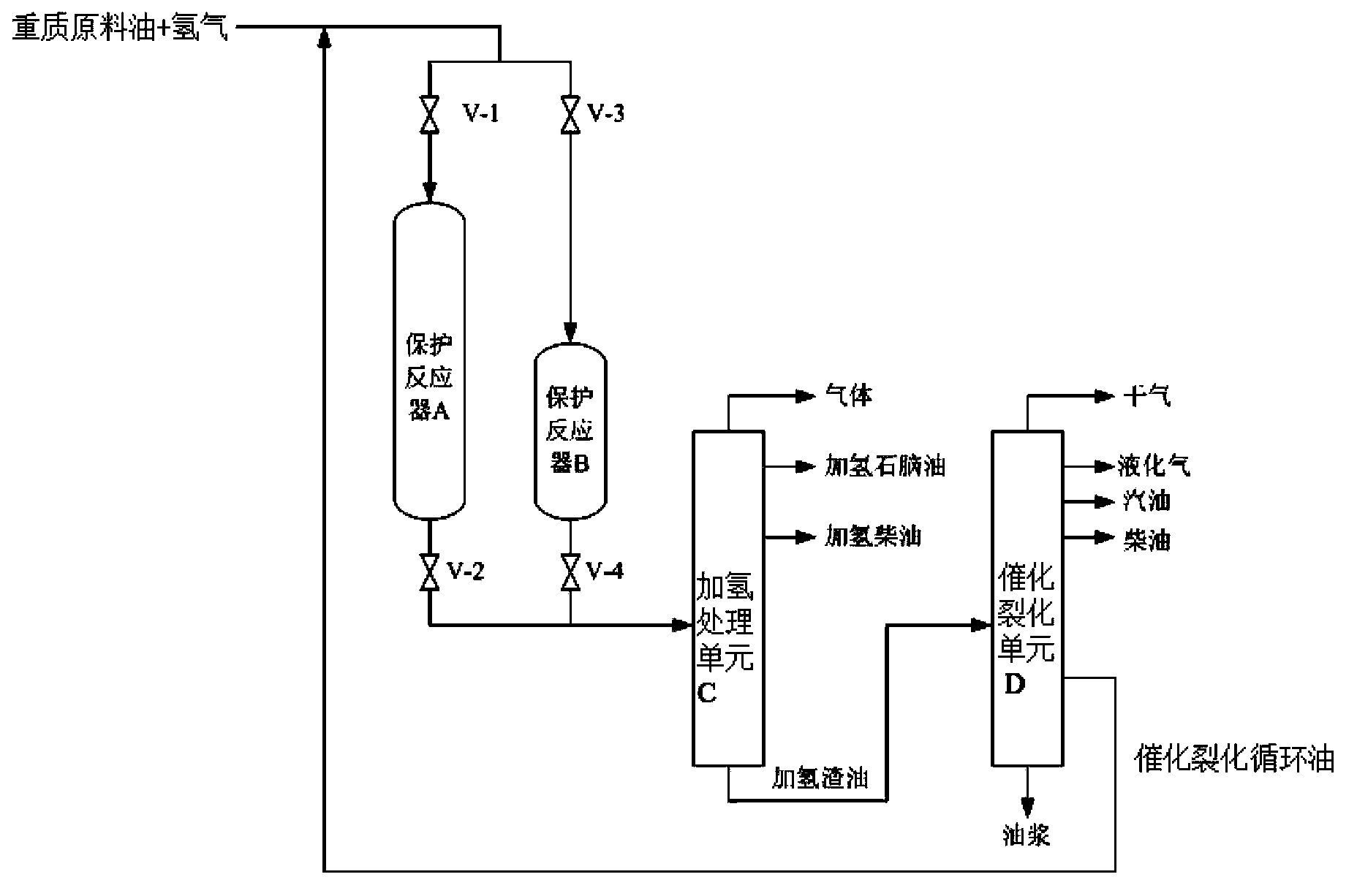
[0057] In the heavy crude oil treatment device used in this example, the main hydrogenation protection reactor is a protection reactor A, the standby hydrogenation protection reactor is a protection reactor B, and the hydroprocessing unit C is a fixed bed slag Oil hydrogenation unit, the catalytic cracking unit D is a laboratory fixed fluidized bed catalytic cracking unit, such as figure 1 shown.

[0058] The protection reactor A is filled with 30mL of RG-20 catalyst, 30mL of RG-30E catalyst, 30mL of RG-30A catalyst and 30mL of RG-30B catalyst, totaling 120mL; the protection reactor B is filled with 10mL of RG-20 catalyst and RG-30E Catalyst 10mL, RG-30A catalyst 10mL and RG-30B catalyst 10mL, 40mL in total; fixed-bed residual oil hydrogenation unit reactor filled with RDM-32 catalyst 200mL, RDM-33 catalyst 200mL, RMS-30 catalyst 200mL and RCS- 30 Catalyst 300mL, total 900mL.

[0059] The trade name of the catalytic cracking catalyst is MLC-500, which is produced by Sinopec ...

Embodiment 2

[0079] The test device of embodiment 2 is the same as that of embodiment 1, and the catalyst type and loading amount of protection reactor A and protection reactor B are the same as that of embodiment 1; The catalyst type and loading amount of the fixed fluidized catalytic cracking unit are the same as those in Example 1.

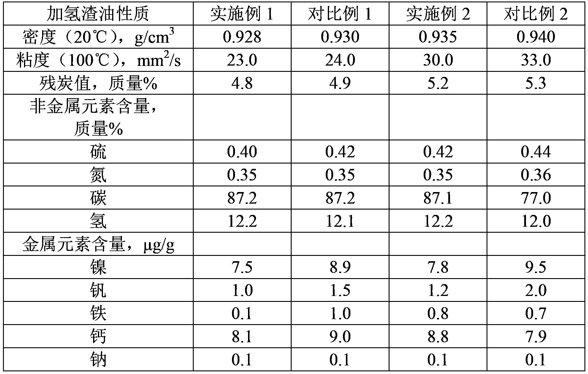
[0080] The raw material oil is atmospheric residue AR, and its properties are shown in Table 1. After AR is mixed with hydrogen, it enters the protection reactor A, and then enters the reactor of the fixed-bed residual oil hydrogenation unit for hydrogenation treatment. The operating conditions are the same as in Example 1, and the properties of the obtained hydrogenated residue are shown in Table 2.

[0081] After entering the residual oil for 1800 hours, the pressure drop of the protective reactor A is close to 0.6MPa, and then the upstream and downstream valves V-3 and V-4 of the reactor B are opened, and at the same time, the upstream and downstream va...


PUM

PropertyMeasurementUnit
volume ratioaaaaaaaaaa

Abstract

The invention provides a heavy raw oil treatment apparatus. The treatment apparatus comprises a hydrogenation protection unit, a hydrotreatment unit and a catalytic cracking unit which are connected in series, wherein the hydrogenation protection unit comprises a main hydrogenation protection reactor and a standby hydrogenation protection reactor which are connected in parallel, and the volume of the main hydrogenation protection reactor is greater than the volume of the standby hydrogenation protection reactor. The invention also provides an application of the heavy raw oil treatment apparatus in the treatment of many oil products, and a method for treating the heavy raw oil by using the heavy raw oil treatment apparatus. Compared with apparatuses in the prior art, the heavy raw oil treatment apparatus adopting the asymmetric switchable protection reactors substantially improves the space utilization rate of the reactors and realizes an obvious economic benefit due to the online time of the larger protection reactor is long and the online time of the smaller protection reactor is short.

Description

technical field [0001] The invention relates to a heavy raw material oil processing device, the application of the heavy raw material oil processing device in the treatment of various oil products, and a heavy raw material oil processing method using the heavy raw material oil processing device. Background technique [0002] At present, the heavy and inferior quality of petroleum resources in the world is becoming more and more serious, and people's demand for clean light oil products is increasing. Therefore, oil refining companies attach great importance to the process of lightening heavy oil. The residual oil hydrogenation-catalytic cracking combined process is an advanced heavy oil lightening method. After the residual oil is hydrotreated to remove heteroatoms such as metals, sulfur, and nitrogen, and to increase the hydrogen content, it can be used as a high-quality catalytic cracking raw material. After the raw material is processed by catalytic cracking, a large amou...

Claims


Application Information

Patent Timeline
Patent Type & Authority Applications(China)
IPC IPC(8): C10G69/00
Inventor 董凯牛传峰戴立顺刘涛邓中活施瑢邵志才杨清河胡大为孙淑玲
Owner CHINA PETROLEUM & CHEM CORP
Learn More