Non-reflux adjustable square cone manifold

A main pipe and flow blocking technology, which is applied in the field of backflow-free and finely adjustable square cone main pipe, can solve the problems of increasing the amount of slurry supplied, increasing the power consumption of the sizing pump, manufacturing and installation errors of the flow blocking elements, etc., and achieves a large adjustment range, Effective and precise adjustment effect, reduced power consumption

Active Publication Date: 2016-05-18
SHAANXI UNIV OF SCI & TECH
View PDF8 Cites 0 Cited by
  • Summary
  • Abstract
  • Description
  • Claims
  • Application Information

AI Technical Summary

Problems solved by technology

The uneven pressure distribution in the conical main pipe comes from the design calculation error (the current calculation formula makes some assumptions or simplification), and the second is that there is often a difference between the actual production flow and the flow parameters used in the design calculation.
[0007] At present, this solution mainly has the following defects: the adjustment of the return flow can only adjust the overall distribution of the pressure in the conical main pipe, but cannot adjust the local pressure, and may not be able to achieve equal pressure in the conical main pipe; even if the conical main pipe The pressure in the pipe is indeed in an equal-pressure distribution, and the slurry flow from the conical main pipe through the flow-blocking elements into the box is not necessarily equal, because the flow-blocking elements still have manufacturing and installation errors; the use of backflow increases the total The amount of slurry supplied increases the power consumption of the sizing pump. Since the adjustment range is limited by the return rate, this limits the adjustable range

Method used


Image

  • Non-reflux adjustable square cone manifold
  • Non-reflux adjustable square cone manifold
  • Non-reflux adjustable square cone manifold

Examples


Embodiment Construction

[0026] The present invention will be described in detail below in conjunction with the accompanying drawings.

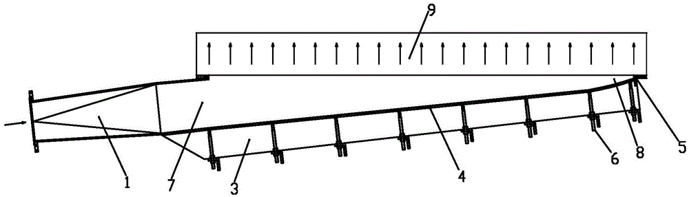
[0027] Such as figure 1 As mentioned above, the present invention provides a finely adjustable square cone manifold without backflow, including a top plate 2 and a bottom plate 3, a movable vertical plate 4 and a slurry distribution blocking element 9 are arranged between the top plate 2 and the bottom plate 3, the top plate 2, the bottom plate 3. The vertical plate 4 and the slurry distribution blocking element 9 form a square conical main pipe cavity, the large end 7 of the square conical main pipe cavity is equipped with a transition pipe 1, and the small end of the square conical main pipe cavity An end plate 5 is installed at the end 8, an inlet is provided on the transition pipe 1, and a small hole is provided on the pulp distributing flow blocking element 9 to allow the pulp to flow out evenly.

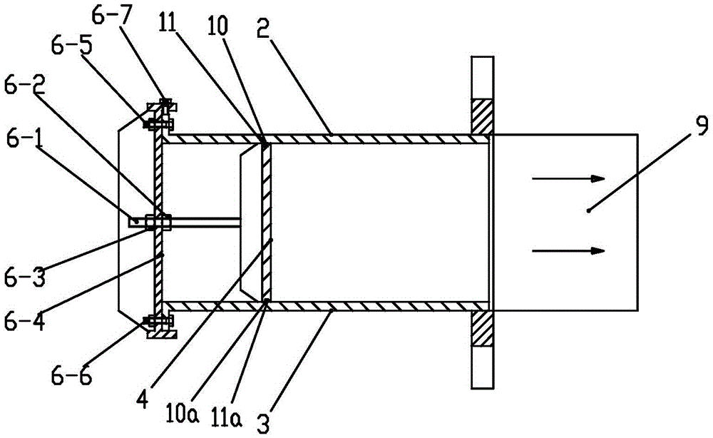
[0028] Such as figure 2 As shown, the vertical plate 4 among ...


PUM


Abstract

The invention provides a non-backflow quadrate-tapered main pipe capable of being adjusted finely. The non-backflow quadrate-tapered main pipe capable of being adjusted finely comprises a top plate and a bottom plate, a movable vertical plate and a pulp-distributing flow-blocking element are arranged between the top plate and the bottom plate, a quadrate-tapered main pipe cavity is formed by the top plate, the bottom plate, the vertical plate and the pulp-distributing flow-blocking element, a transition pipe is arranged at the large end of the quadrate-tapered main pipe cavity, an end plate is arranged at the small end of the quadrate-tapered main pipe cavity, the transition pipe is provided with an inlet, and the pulp-distributing flow-blocking element is provided with small holes allowing paper pulp to flow out evenly. According to the non-backflow quadrate-tapered main pipe capable of being adjusted finely, an existing backflow device can be omitted, the total pump supply amount can be reduced, power consumption of a pump feeding pump can be reduced, the amplitude of power consumption reduction is roughly consistent with the backflow rate, and compared with a backflow adjusting mode, the non-backflow quadrate-tapered main pipe capable of being adjusted finely is larger in adjusting range.

Description

technical field [0001] The invention belongs to a headbox in a papermaking machine, relates to a conical pulp distributor, in particular to a backflow-free and finely adjustable square cone main pipe. Background technique [0002] One of the basic tasks of the headbox is to ensure that the fiber suspension is evenly distributed along the transverse direction of the paper machine, so as to minimize the transverse weight difference of the paper sheet. The pulp distributor is an integral part of the headbox, and its function is to distribute the pulp evenly into the box of the headbox along the transverse direction of the paper machine. [0003] The paper machine adopts the existing headbox. When it is necessary to adjust the banner weight of the paper sheet, it is generally carried out by adjusting the fine adjustment of the upper lip plate or the adjustment of the dilution water. However, sometimes it is found that no amount of adjustment can meet the uniform banner weight re...

Claims


Application Information

Patent Timeline
Patent Type & Authority Patents(China)
IPC IPC(8): D21F1/06
Inventor 侯顺利
Owner SHAANXI UNIV OF SCI & TECH
Why Eureka
Try Eureka