
Gap compensation clutch retainer ring mechanism of hydraulic brake

A hydraulic brake and gap compensation technology, applied in the direction of the slack adjuster, etc., can solve the problems of slow clutch separation response, insufficient brake braking pressure, insufficient plunger pressure, etc., to achieve good anti-vibration effect, timely compensation, plunger even pressure effect

Inactive Publication Date: 2014-10-29
XUZHOU CONTENT TRANSMISSION TECH
View PDF0 Cites 0 Cited by
  • Summary
  • Abstract
  • Description
  • Claims
  • Application Information

AI Technical Summary

Problems solved by technology

[0003] The purpose of the present invention is to provide a hydraulic brake gap compensation clutch collar mechanism to solve the above-mentioned clutch collar mechanism that is easy to fall off, resulting in insufficient braking pressure during the brake movement, insufficient plunger pressure, and slow clutch separation response. Defects

Method used


Image

  • Gap compensation clutch retainer ring mechanism of hydraulic brake

Examples


Embodiment Construction

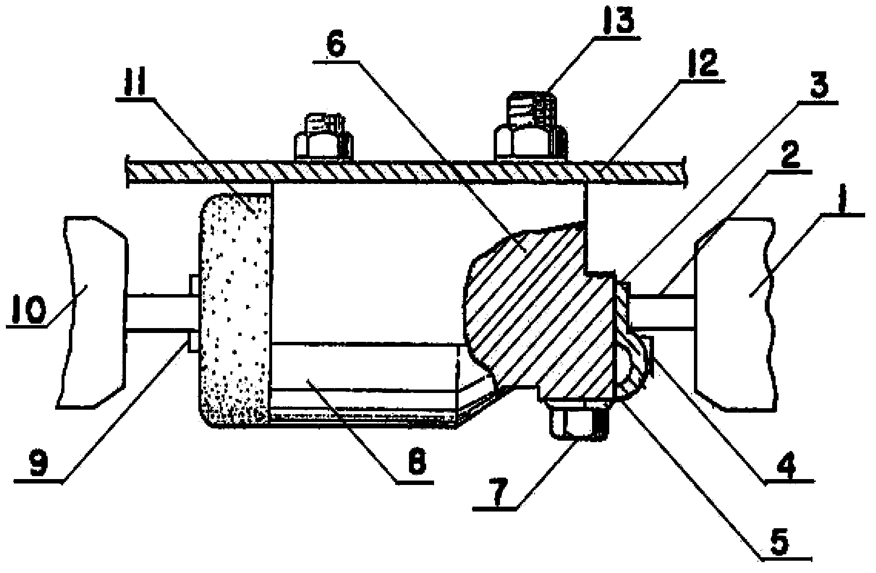
[0009] The clutch collar mechanism has a cylinder (11), an engagement groove (9) is arranged at one end of the cylinder (11), and a plunger (8) is installed in the engagement groove (9) and the inner cavity of the cylinder (11) , one end of the plunger (8) is connected with the right brake shoe (10) through the engagement groove (9), and the other end is connected with the clutch (6), and a connecting plate (3) is arranged at the left end of the clutch (6), One end of the shoe web (2) is connected to the clutch (6) through the connecting plate (3), and the other end is connected to the left brake shoe (1), and half of the S-shaped collar (5) is set on the connecting plate (3) , the half S-shaped collar (5) is fixed on the connecting plate (3) by the retainer (4) through the positioning bolt (7), and a double fixing plate (12) is arranged on the cylinder body (11), and the double fixing plate (12) is fixed on the cylinder block (11) by bolts (13).


PUM


Abstract

Provided is a gap compensation clutch retainer ring mechanism of a hydraulic brake. A meshing groove is formed in one end of a cylinder body, plunger pistons are installed in the meshing groove and the inner cavity of the cylinder body, one end of each plunger piston is connected with a right bake shoe through the meshing groove, the other end of each plunger piston is connected with a clutch, and a connecting plate is arranged at the left end of the clutch. One end of a shoe web plate is connected with the clutch through the connecting plate, the other end of the shoe web plate is connected with a left brake shoe, a semi-S-shaped retainer ring is arranged on the connecting plate and fixed on the connecting plate through a retainer and a positioning bolt, a dual-fixing plate is arranged on the cylinder body and fixed on the cylinder body through a stud.

Description

technical field [0001] The invention relates to a clutch collar mechanism, in particular to a hydraulic brake gap compensation clutch collar mechanism, which belongs to the technical field of hydraulic brakes. Background technique [0002] Hydraulic brake gap compensation clutch collar mechanism is an important part of the machine to stop and decelerate the moving parts. Its main parts are composed of frame, brake parts, control parts and clutch device. Its characteristics are: compact structure, small size , large torque, long service life, etc. However, due to the vertical fastening structure of the hoof web, connecting plate and retainer in the prior art, the collar is easy to fall off during vibration, resulting in insufficient braking pressure of the compensating clutch during motion, and the plunger The pressure is not enough, and the clutch disengagement response is not fast. Contents of the invention [0003] The purpose of the present invention is to provide a h...

Claims


Application Information

Patent Timeline
Patent Type & Authority Applications(China)
IPC IPC(8): F16D65/40
Inventor 藏继民
Owner XUZHOU CONTENT TRANSMISSION TECH
Learn More