One-way loop gravity assisted heat pipe and manufacturing method thereof

A technology of gravity heat pipe and loop heat pipe, applied in indirect heat exchangers, lighting and heating equipment, etc., can solve the problems of low heat transfer efficiency, slow start, uncertain flow direction, etc., to achieve low cost, high efficiency utilization, structure compact effect

Active Publication Date: 2014-10-29
INST OF ENGINEERING THERMOPHYSICS - CHINESE ACAD OF SCI
View PDF10 Cites 14 Cited by
  • Summary
  • Abstract
  • Description
  • Claims
  • Application Information

AI Technical Summary

Problems solved by technology

[0003] In view of this, the object of the present invention is to provide a unidirectional loop gravity heat pipe and its manufacturing method that can make the working fluid inside the heat pipe have unidirectional flowability (hereinafter referred to as "unidirectionality") during work, so as to overcome the " Two-headed", slow start-up, and low heat transfer efficiency due to uncertain flow direction

Method used


Image

  • One-way loop gravity assisted heat pipe and manufacturing method thereof
  • One-way loop gravity assisted heat pipe and manufacturing method thereof
  • One-way loop gravity assisted heat pipe and manufacturing method thereof

Examples


Embodiment 1

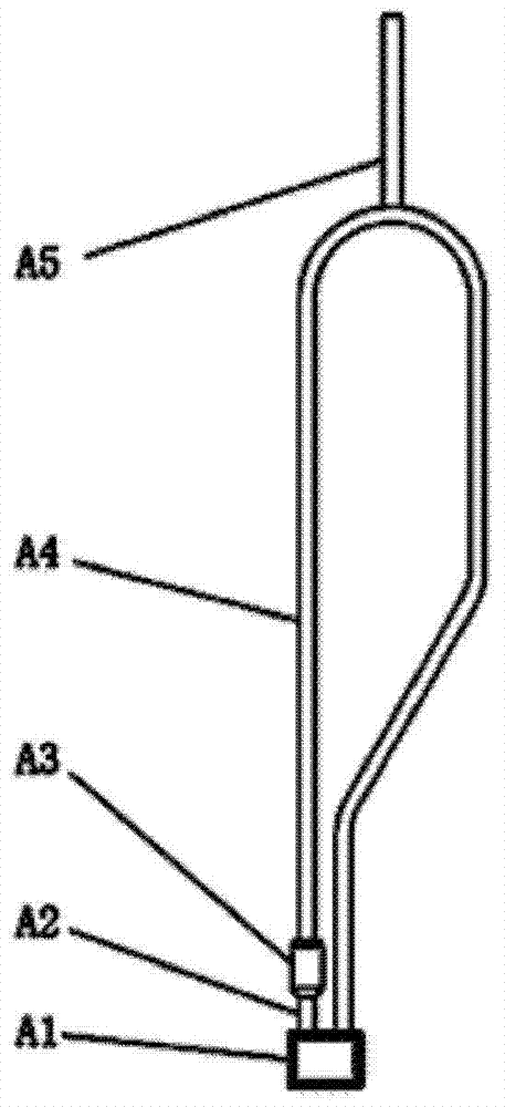
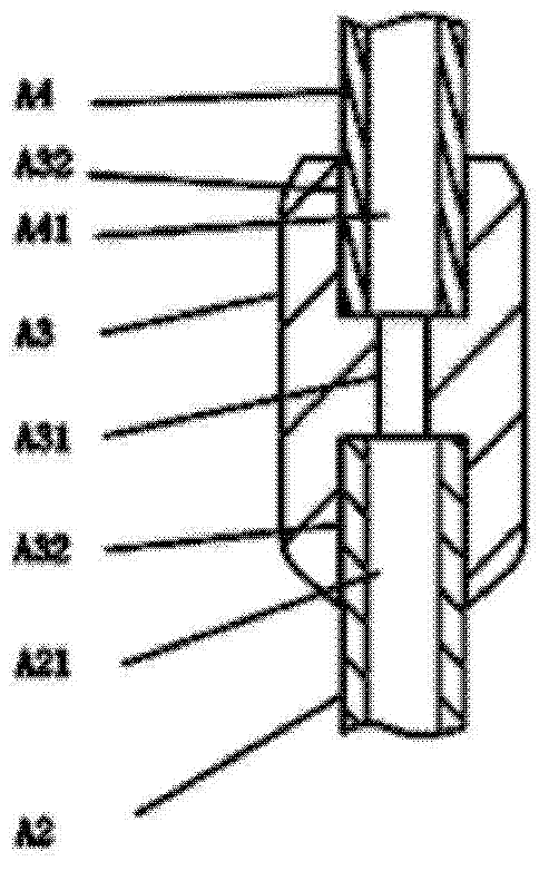
[0040] Such as figure 1 As shown, the basic structure of a one-way loop gravity heat pipe shell according to the present invention includes: a liquid bag A1, a short connecting pipe A2, a shrinking and reducing joint A3, a long connecting pipe A4 and a liquid filling port A5. Among them, the liquid bag A1, the short connecting pipe A2, the shrinking and reducing joint A3, and the long connecting pipe A4 all use the same metal material, and are welded in sequence to form a loop; wherein, the internal structure of the shrinking and reducing joint A3 is as follows: figure 2 As shown, the upper end connecting channel A32 of the internal shrinking pipe A31 is connected to the long connecting pipe A4, and the lower end connecting channel A32 of the shrinking pipe A31 is connected to the short connecting pipe A2; the diameter of the shrinking pipe A31 is smaller than the internal pipe A41 of the long connecting pipe. and the diameter of the inner pipe A21 of the short connecting pip...

Embodiment 2

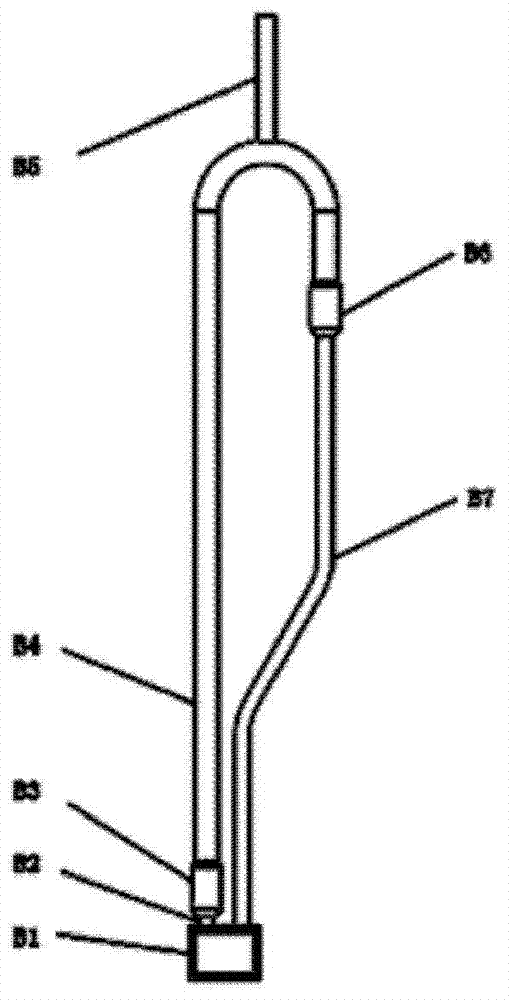
[0043] The one-way loop gravity heat pipe of the present invention can also be made of metal pipes with different diameters. Such as image 3 As shown, in some occasions, due to the limitation of space and heating end, the short connecting pipe B2 connected with the liquid bag and the long connecting thin pipe B7 must use the same specification and thinner diameter metal pipes. In order to enhance heat dissipation and reduce the flow resistance of the working fluid in the heat dissipation pipeline, it is often necessary to introduce a thicker long connecting thick pipe B4 into the heat pipe loop that plays a role in heat dissipation to form a flared variable diameter joint B6 and a narrowed joint B6. The heat dissipation loop of the thick and thin tubes of the reducing joint B3. Thus, the shell of a one-way loop gravity heat pipe according to the present invention can be composed of a liquid bag B1, a short connecting pipe B2, a shrinking and reducing joint B3, a long connect...


PUM


Abstract

The invention discloses a one-way loop gravity assisted heat pipe. The one-way loop gravity assisted heat pipe comprises a liquid bag, a short connecting pipe, a necking down reducer union and a long connecting pipe. The invention further discloses a manufacturing method of the one-way loop gravity assisted heat pipe. The necking down reducer union is added in the loop gravity assisted heat pipe to achieve a necking down structure to enable the flowing direction of a working medium in the loop gravity assisted heat pipe to be uniquely determined during working, in other words, the whole heat pipe shows the one-way performance, and therefore the one-way loop gravity assisted heat pipe is started more rapidly compared with an ordinary loop gravity assisted heat pipe, and the heat of a heat dissipation end is more efficiently utilized. In addition, the heated end of the one-way loop gravity assisted heat pipe is located at the bottommost end of the heat pipe, and therefore the one-way loop gravity assisted heat pipe has wide applicability, and is compact in structure and low in cost.

Description

technical field [0001] The present invention relates to the field of heat transfer equipment, and more particularly to a gravity heat pipe, especially a loop gravity heat pipe, and a manufacturing method thereof. Background technique [0002] The heat pipe is a heat transfer element that relies on the phase change of its internal working liquid to transfer heat. It has the advantages of high thermal conductivity, excellent isothermal property, and wide environmental adaptability. Gravity heat pipe, also known as thermosiphon, relies on gravity difference to realize heat pipe function. The gravity heat pipe is a heat pipe without a liquid-absorbing core, so the structure is relatively simple and the cost is low, and it has been widely used at present. There must be a complete circuit inside the heat pipe for the circulation of the working fluid, which is a necessary condition for the normal operation of the gravity heat pipe. The loop gravity heat pipe passes through the lo...

Claims


Application Information

Patent Timeline
Patent Type & Authority Applications(China)
IPC IPC(8): F28D15/02
Inventor 李铁桂小红刘强姜玉雁唐大伟
Owner INST OF ENGINEERING THERMOPHYSICS - CHINESE ACAD OF SCI
Why Eureka
Try Eureka