Vacuum sealing structure of uniform temperature heat conduction device and its manufacturing method

A vacuum and method technology, applied in the direction of indirect heat exchangers, lighting and heating equipment, etc., can solve the problems of complex manufacturing process, influence of ideal shape, solder pollution and unenvironmental protection, etc.

Inactive Publication Date: 2016-04-13
SUZHOU FORCECON ELECTRIC
View PDF6 Cites 0 Cited by
  • Summary
  • Abstract
  • Description
  • Claims
  • Application Information

AI Technical Summary

Problems solved by technology

[0003] The disadvantage is that the structural shape and molding method of the above-mentioned existing uniform temperature heat conduction device still have some problems and disadvantages in practical application experience. The reason is that the gap is usually used to punch out the three-dimensional cover by using the upper cover plate. The shape of the shell is formed by punching out a half-pipe shape around its periphery. After being stacked and combined with the lower cover plate, a gap with an opening facing the side is formed. However, the design of the gap does not conform to the shape of the side opening In addition to the shortcomings of the mechanism of the related processing equipment, the setting of the gap will affect the ideal shape of the upper and lower cover plates that can be closed in a ring shape, causing the internal vacuum state to be easily damaged and lost. It is maintained for a long time, and because the gap must be closed by soldering after completing the steps of vacuuming and liquid injection, the manufacturing process is somewhat complicated, and the use of the solder has many problems such as pollution and environmental protection.

Method used


Image

  • Vacuum sealing structure of uniform temperature heat conduction device and its manufacturing method
  • Vacuum sealing structure of uniform temperature heat conduction device and its manufacturing method
  • Vacuum sealing structure of uniform temperature heat conduction device and its manufacturing method

Examples


Embodiment

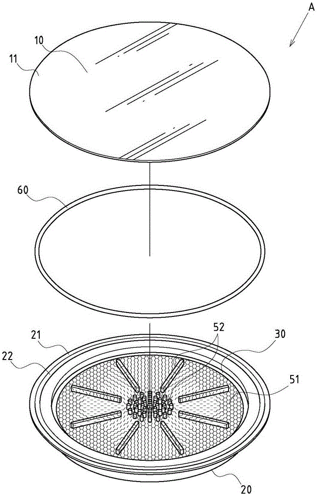
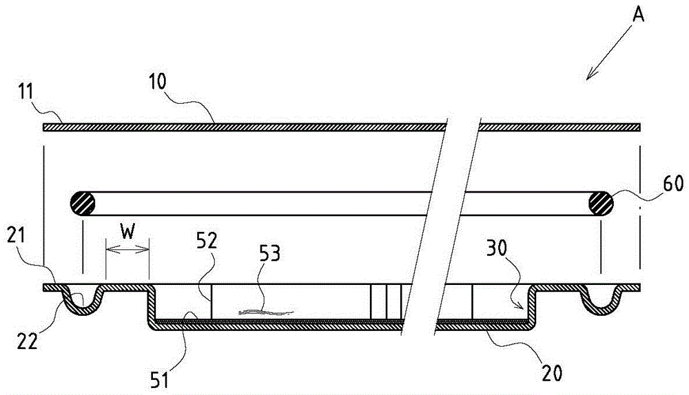
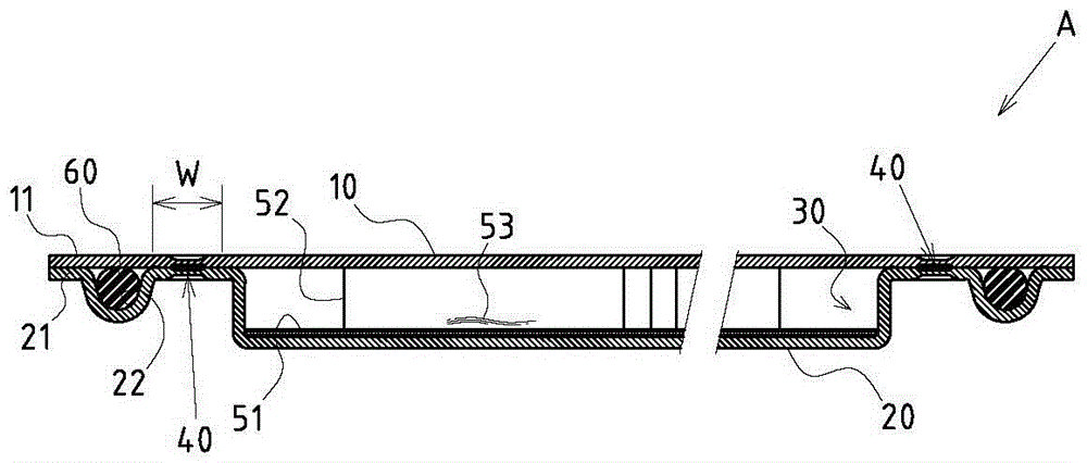
[0042] Example: see Figure 1~4 Shown is the preferred embodiment of the vacuum sealing structure of the uniform temperature heat conduction device of the present invention and its manufacturing method. These embodiments are for illustration purposes only, and are not limited by this structure in the patent application; The heat conduction device A is formed by stacking an upper cover plate 10 and a lower cover plate 20. A vacuum-enclosed hollow chamber 30 is formed inside between the upper cover plate 10 and the lower cover plate 20. The surrounding area of ​​the upper cover plate 10 is There is an upper sealing ring 11 facing horizontally, and a lower sealing ring 21 facing horizontally is arranged around the lower cover plate 20, forming a gap between the upper sealing ring 11 and the lower sealing ring 21. There is a torus-like abutment relationship between the upper and lower directions, and has a width for welding (such as image 3 marked by W); and between the surface ...


PUM


Abstract

A vacuum sealing structure of a uniform heat conductor and a making method thereof; an upper cover plate and a lower cover plate are arranged; a periphery of the upper cover plate is provided with an upper sealing annular edge; a periphery of the lower cover plate is provided with a lower sealing annular edge having an annular slot; an elastic stop sealing ring is assembled in the annular slot; the upper and lower cover plates are placed in a vacuum device, so the upper cover plate is clamped on the lower cover plate in vacuum environment condition; when the upper cover plate covers on the lower cover plate, the elastic stop sealing ring can be pressed to deform and expand, so sealing state can be formed between the upper and lower sealing annular edges; the upper and lower cover plates are then removed, and inner intervals of the elastic stop sealing ring positions of the upper and lower sealing annular edges are welded and bonded in an annular continuous welding mode, thus forming a solderless annular continuous welding bonding portion in a continuous annular welding bonding state; the vacuum sealing structure has simplified production process, reduces making cost, has practical advanced feature and better industry economic benefits.

Description

technical field [0001] The invention relates to a temperature uniform heat conduction device, in particular to an innovative design of a vacuum sealing structure and a manufacturing method of a temperature uniform heat conduction device. Background technique [0002] The structural form of the existing uniform temperature heat conduction device is usually composed of an upper cover plate and a lower cover plate stacked against each other, and the periphery of the two is combined and fixed; and the periphery of the upper cover plate and the lower cover plate is in the After the joining and fixing steps are completed, usually a gap must be reserved for subsequent steps such as vacuuming and liquid injection inside the uniform temperature heat conduction device, and then the gap is closed by soldering. [0003] The disadvantage is that the structural form and molding method of the above-mentioned existing uniform temperature heat conduction device still have some problems and d...

Claims


Application Information

Patent Timeline
Patent Type & Authority Patents(China)
IPC IPC(8): F28D15/04
Inventor 饶振奇何信威黄志仁
Owner SUZHOU FORCECON ELECTRIC
Why Eureka
Try Eureka