Method and system for testing high-speed optical module

A test method and technology for optical modules, applied in transmission monitoring/testing/fault measurement systems, etc., can solve the problems of increasing the production cost and high price of optical modules

Inactive Publication Date: 2014-10-29
SHENZHEN GONGJIN ELECTRONICS CO LTD
View PDF3 Cites 22 Cited by
  • Summary
  • Abstract
  • Description
  • Claims
  • Application Information

AI Technical Summary

Problems solved by technology

Among these devices, the price of the bit error analyzer and the optical attenuator is generally not too high, but the eye diagram instrument occupies a very important position in the production of all 10G optical modules, not only referring to the necessity of production, but also its high cost. For the optical module production line produced in large quantities, a large number of additional eye diagram instruments will obviously increase the production cost of optical modules

Method used


Image

  • Method and system for testing high-speed optical module
  • Method and system for testing high-speed optical module
  • Method and system for testing high-speed optical module

Examples


Embodiment 1

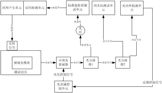
[0057] Example 1, such as figure 1 As shown, this embodiment is a method for measuring the extinction ratio and bit error rate of a signal of a high-speed optical module such as a 10G optical module and a system for implementing the method.

[0058] For the production of 10G optical modules, the function of the eye diagram instrument is to test the extinction ratio of the optical module and the quality of the eye diagram. This embodiment provides a method for testing the extinction ratio and the quality of the eye diagram, which is used for mass production lines Production debugging of optical modules.

[0059] The functions of each functional circuit in the above figure are as follows:

[0060] 1. Code generation unit: used to generate pseudo-random codes and output them. You can use special equipment or special chips. We choose Siliconlab’s Si5040 chip, which can generate PRBS codes at a rate of 10G. We pass MCU controls Si5040, generates the pattern and rate we need, and ...


PUM


Abstract

The invention provides a method and a system for testing a high-speed optical module. The method comprises the steps of receiving an optical signal sent by the tested high-speed optical module, measuring the OMA (Optical Modulation Amplitude) and optical power of the optical signal, obtaining an extinction ratio by virtue of calculation, if the extinction ratio complies with the product specification, performing error code testing on the tested high-speed optical module, adopting a standard receiving tube test unit to receive an optical signal with a pseudo-random signal from the tested high-speed optical module while testing error codes, and carrying out demodulation on the optical signal by use of the standard receiving tube test unit and then carrying out comparison, thereby finishing the error rate testing.

Description

technical field [0001] The invention relates to the field of production and testing of optical communication equipment, in particular to a method for testing high-speed optical signal eye diagrams and a high-speed optical module detection system when producing high-speed optical communication products. Background technique [0002] The types of 10G optical modules can be roughly divided into data network applications and telecom network applications. Among them, the transmission distance of data network optical modules is short, and the products are relatively simple. The equipment used in production includes: [0003] 1. Bit error analyzer; [0004] 2. Optical attenuator; [0005] 3. Eye diagram instrument; [0006] 4. Other auxiliary devices such as computers, test fixtures, light sources, optical fiber jumpers, etc. [0007] Optical modules used in telecommunication networks are generally used for long-distance transmission, among which DWDM Dense Wavelength Division M...

Claims


Application Information

Patent Timeline
Patent Type & Authority Applications(China)
IPC IPC(8): H04B10/07
Inventor 王彦伟王侃
Owner SHENZHEN GONGJIN ELECTRONICS CO LTD
Why Eureka
Try Eureka