

Compacting die for refractory brick
A technology for pressing molds and refractory bricks, which is applied in the field of pressing molds, and can solve the problems of insufficient height of annular ribs of refractory bricks
- Summary
- Abstract
- Description
- Claims
- Application Information
AI Technical Summary
Problems solved by technology
Method used
Image

Examples
Embodiment Construction
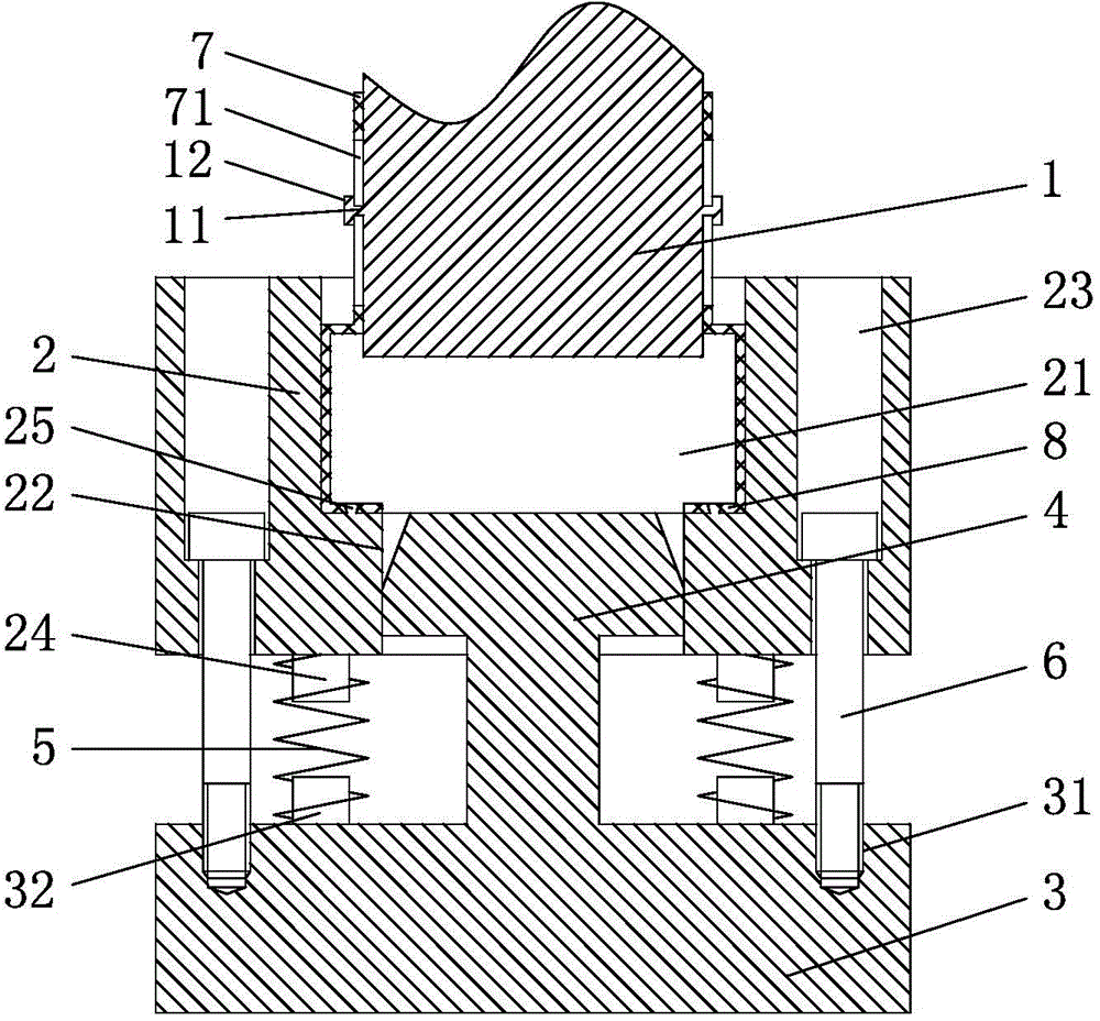
[0021] refer to figure 1 , a pressing die for refractory bricks, including a punch 1 and a die assembly, the die assembly includes a forming die 2, a fixing seat 3, a return spring 5 and a bolt 6, and the bolt 6 is threaded with the fixing seat 3 after passing through the forming die 2 Connected, the bottom end surface of forming mold 2 is provided with the first limiting block 24, and one end of return spring 5 is sleeved on the first limiting block 24 and touches the bottom end surface of forming mold 2, and the top end surface of fixing base 3 is provided with the second The limiting block 32 , the other end of the return spring 5 is sleeved on the second limiting block 32 and contacts the top surface of the fixing seat 3 .
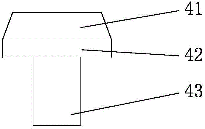
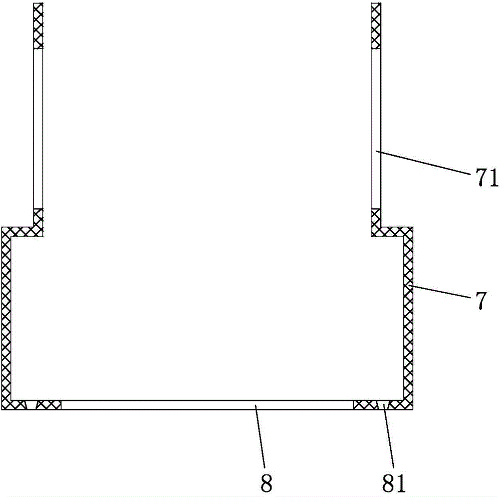
[0022] refer to figure 1 , figure 2 and image 3 , the forming die 2 is provided with a forming groove 21, the diameter of the punch 1 is 8mm smaller than the diameter of the forming groove 21, the bottom wall of the forming groove 21 is provided w...
PUM
| Property | Measurement | Unit |
|---|---|---|
| height | aaaaa | aaaaa |
| height | aaaaa | aaaaa |
Abstract
Description
Claims
Application Information