A limit mechanism for automatic feeding device of disc-shaped parts

A technology of automatic feeding and limit mechanism, applied in the direction of conveyor objects, transportation and packaging, etc., can solve the problems of workpiece slipping, inaccurate feeding control, and affecting the normal operation of automatic lines, so as to improve production efficiency, use convenient and reliable, and structure simple effect

Active Publication Date: 2016-01-13
德清县宝华氟塑料工贸有限公司
View PDF11 Cites 0 Cited by
  • Summary
  • Abstract
  • Description
  • Claims
  • Application Information

AI Technical Summary

Problems solved by technology

[0002] In the prior art, the automatic feeding device of the disc-shaped parts such as the piston bowl basically uses a vibrating disc to automatically feed the material. When the disc-shaped parts are fed into the groove of the feeding push rod, if the equipment stops or the time is not properly controlled, the disc-shaped parts are the workpiece. It will roll out along the side baffle, causing uncertain factors such as workpiece slipping and inaccurate feeding control, which will affect the normal operation of the automatic line

Method used


Image

  • A limit mechanism for automatic feeding device of disc-shaped parts
  • A limit mechanism for automatic feeding device of disc-shaped parts
  • A limit mechanism for automatic feeding device of disc-shaped parts

Examples


Embodiment Construction

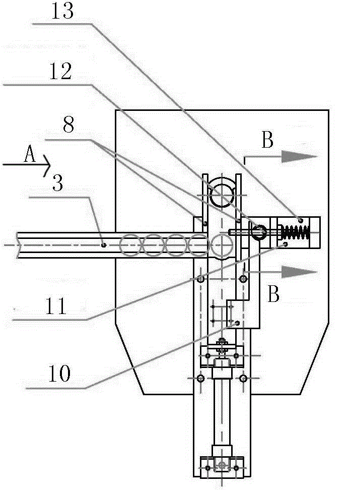
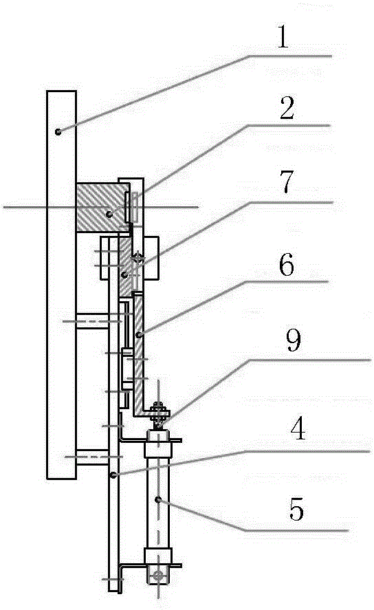
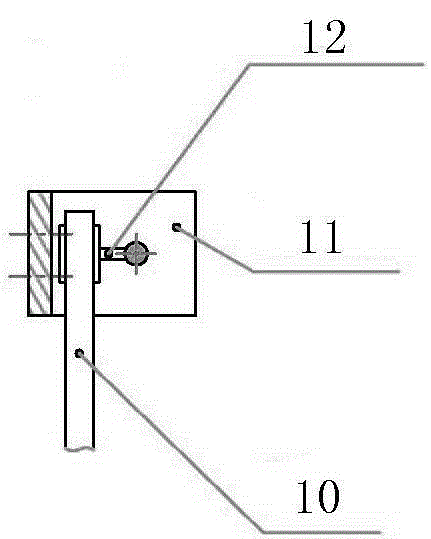
[0012] The present invention will be described in detail below in conjunction with accompanying drawing: Figure 1-3 As shown, the automatic feeding device of the present invention includes a working table 1, a station base 2, a feeding track 3, a feeding cylinder base 4, a feeding cylinder group 5, a feeding push plate 6, a feeding pallet 7, and two side baffles 8 , the feeding cylinder base 4 is fixedly installed on the work surface 1, the feeding cylinder group 5 is fixedly installed on the feeding cylinder base 4, one end of the feeding push plate 6 is fixedly connected with the feeding cylinder push rod 9, and the feeding can be carried out under the thrust of the cylinder. The workpiece in the groove of the push plate 6 is fed forward, the feed pallet 7 is fixedly installed on the feed cylinder base 4, the side baffles 8 on both sides are fixedly mounted on the side of the feed pallet 7, the head end of the feed rail 3 is connected with the feed push plate 6 notches; one...


PUM


Abstract

The invention discloses a limiting mechanism applied to an automatic feeding device for disk parts. The automatic feeding device comprises a working table facet, a position base, a feeding track, a feeding cylinder base, a feeding cylinder set, a feeding push plate, a feeding supporting plate and two side baffles, wherein the feeding cylinder base is fixedly mounted on the working table facet, the feeding cylinder set is fixedly mounted on the feeding cylinder base, one end of the feeding push plate is fixedly connected with a feeding cylinder push rod, a workpiece in a groove of the feeding push plate can be fed forwards under the cylinder thrust, the feeding supporting plate is fixedly mounted on the feeding cylinder base, the two side baffles are fixedly mounted on the side faces of the feeding supporting plate, and the head end of the feeding track is connected with a notch of the feeding push plate. The limiting mechanism mainly composed of a limiting push rod, a limiting pin base and a limiting pin combination piece is additionally mounted on one side of the automatic feeding device, wherein the limiting pin base is fixedly mounted on the feeding cylinder base, the limiting push rod is fixedly mounted on the feeding push plate, one end of the limiting pin combination piece penetrates through one side baffle, the other end of the limiting pin combination piece penetrates through a baffle of the limiting pin base, and a limiting spring is arranged at one end of a limiting pin in a sleeved mode and abuts against the rear baffle of the limiting pin base.

Description

technical field [0001] The invention relates to a limit mechanism for an automatic feeding device for disc-shaped parts, and belongs to the technical field of feeding machinery. Background technique [0002] In the prior art, the automatic feeding device of the disc-shaped parts such as the piston bowl basically uses a vibrating disc to automatically feed the material. When the disc-shaped parts are fed into the groove of the feeding push rod, if the equipment stops or the time is not properly controlled, the disc-shaped parts are the workpiece. It will roll out along the side baffle, causing uncertain factors such as workpiece slipping and inaccurate feeding control, which will affect the normal operation of the automatic line. Contents of the invention [0003] The purpose of the present invention is to overcome the deficiencies in the prior art, and provide a simple and reasonable structure, convenient and reliable to use, which can ensure your accurate feeding and impr...

Claims


Application Information

Patent Timeline
Patent Type & Authority Patents(China)
IPC IPC(8): B65G47/74
Inventor 鄢和平蔡斌
Owner 德清县宝华氟塑料工贸有限公司
Why Eureka
Try Eureka