Underground diaphragm wall grooving quality detecting device with electronic compass and underground diaphragm wall grooving quality detecting method

An underground diaphragm wall and detection device technology, which is applied in the field of foundation soil survey, foundation structure test, construction, etc., can solve the problems of difficult determination of accurate values, weak acoustic reflection signals, and bulky detection equipment, etc., and achieve accurate detection results and reliable results

Active Publication Date: 2014-11-05
武汉岩海工程技术有限公司
View PDF6 Cites 12 Cited by
  • Summary
  • Abstract
  • Description
  • Claims
  • Application Information

AI Technical Summary

Problems solved by technology

[0022] However, in practical applications, the successful application of the sonic method has great limitations, mainly because:
[0023] ①The tank is full of mixed water, and many mud particles suspended in it can easily cause physical phenomena such as scattering and diffusion of the acoustic signal, resulting in the attenuation of the propagation energy of the acoustic signal, so the acoustic reflection signal is weak;
[0026] ④ The propagation speed of sound waves in mixed water medium should be slightly smaller than that in pure water, but the actual accurate value is not easy to determine, which will affect the calculation accuracy of sound wave propagation distance
[0027] ⑤This type of testing equipment is bulky, difficult to carry, and expensive

Method used


Image

  • Underground diaphragm wall grooving quality detecting device with electronic compass and underground diaphragm wall grooving quality detecting method
  • Underground diaphragm wall grooving quality detecting device with electronic compass and underground diaphragm wall grooving quality detecting method
  • Underground diaphragm wall grooving quality detecting device with electronic compass and underground diaphragm wall grooving quality detecting method

Examples


Embodiment Construction

[0098] Below in conjunction with accompanying drawing and embodiment the present invention is described in detail:

[0099] 1. Device

[0100] 1. Overall

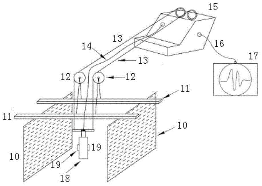
[0101] Such as Figure 4 , the device comprises an underground diaphragm wall 10 (object to be measured), a support 11, a pulley 12, a signal cable 14, and a host connection 16;

[0102] A new electric winch 20 and a new host 21 are replaced, and a new downhole probe 100 is installed;

[0103] Its location and connection relationship are:

[0104] A support 11 is provided at the notch of the underground continuous wall 10, and a pulley 12 is provided on the support 11;

[0105] The low end of the signal cable 14 is connected with the novel downhole probe 100, and the high end of the signal cable 14 is connected with the novel electric winch 20 through the pulley 12;

[0106] Novel electric winch 20 is connected on the novel main engine 21 by main engine connecting line 16.

[0107] 2. Functional components

[0108] 1...


PUM


Abstract

The invention discloses an underground diaphragm wall grooving quality detecting device with an electronic compass and an underground diaphragm wall grooving quality detecting method, and relates to the constructional engineering detecting technology. The underground diaphragm wall grooving quality detecting device with the electronic compass comprises an underground diaphragm wall, a support, a pulley, a signal cable and a main engine connecting line, and is provided with a novel electric winch, a novel main engine and a novel underground probe, wherein the support is arranged in a grooving opening of the underground diaphragm wall; the pulley is arranged on the support; the lower end of the signal cable is connected with the novel underground probe; the higher end of the signal cable is connected with the novel electric winch via the pulley; and the novel electric winch is connected to the novel main engine through the main engine connecting line. By the mechanical contact mode, the underground diaphragm wall grooving quality detecting method is more direct than the traditional sound wave method, so that detection results are accurate and reliable; and the underground diaphragm wall grooving quality detecting device with the electronic compass and the underground diaphragm wall grooving quality detecting method are suitable for detecting the quality of grooving of underground diaphragm walls.

Description

technical field [0001] The invention relates to construction engineering detection technology, in particular to an underground continuous wall groove quality detection device with an electronic compass and a method thereof. Background technique [0002] The underground diaphragm wall is used in construction engineering, using special trenching equipment, under the condition of mud retaining wall, to excavate a groove section with a certain length, width and depth underground, place a steel cage, and pour concrete; then connect each groove section, Form a continuous underground reinforced concrete wall. Its main function: [0003] ①Cut off the groundwater to create conditions for the construction in the foundation pit; [0004] ② To withstand the lateral pressure of the surrounding soil; [0005] ③ Used as a wall function; [0006] ④As part of the foundation foundation, to bear the upper load. [0007] At present, the underground diaphragm wall has been widely used in an...

Claims


Application Information

Patent Timeline
Patent Type & Authority Applications(China)
IPC IPC(8): E02D33/00E02D1/00
Inventor 杨燕军
Owner 武汉岩海工程技术有限公司
Why Eureka
Try Eureka