Crown ball control valve of high-pressure common-rail oil injector
A high-pressure common rail and fuel injector technology, used in machines/engines, fuel injection devices, engine components, etc., can solve the problems of unreliable sealing, small size of the inner concave spherical surface, and high precision, and improve high-pressure sealing and processing. The effect of low difficulty and high machining accuracy
- Summary
- Abstract
- Description
- Claims
- Application Information
AI Technical Summary
Problems solved by technology
Method used
Image
Examples
Embodiment 1
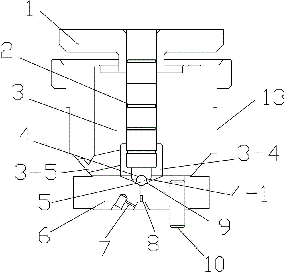
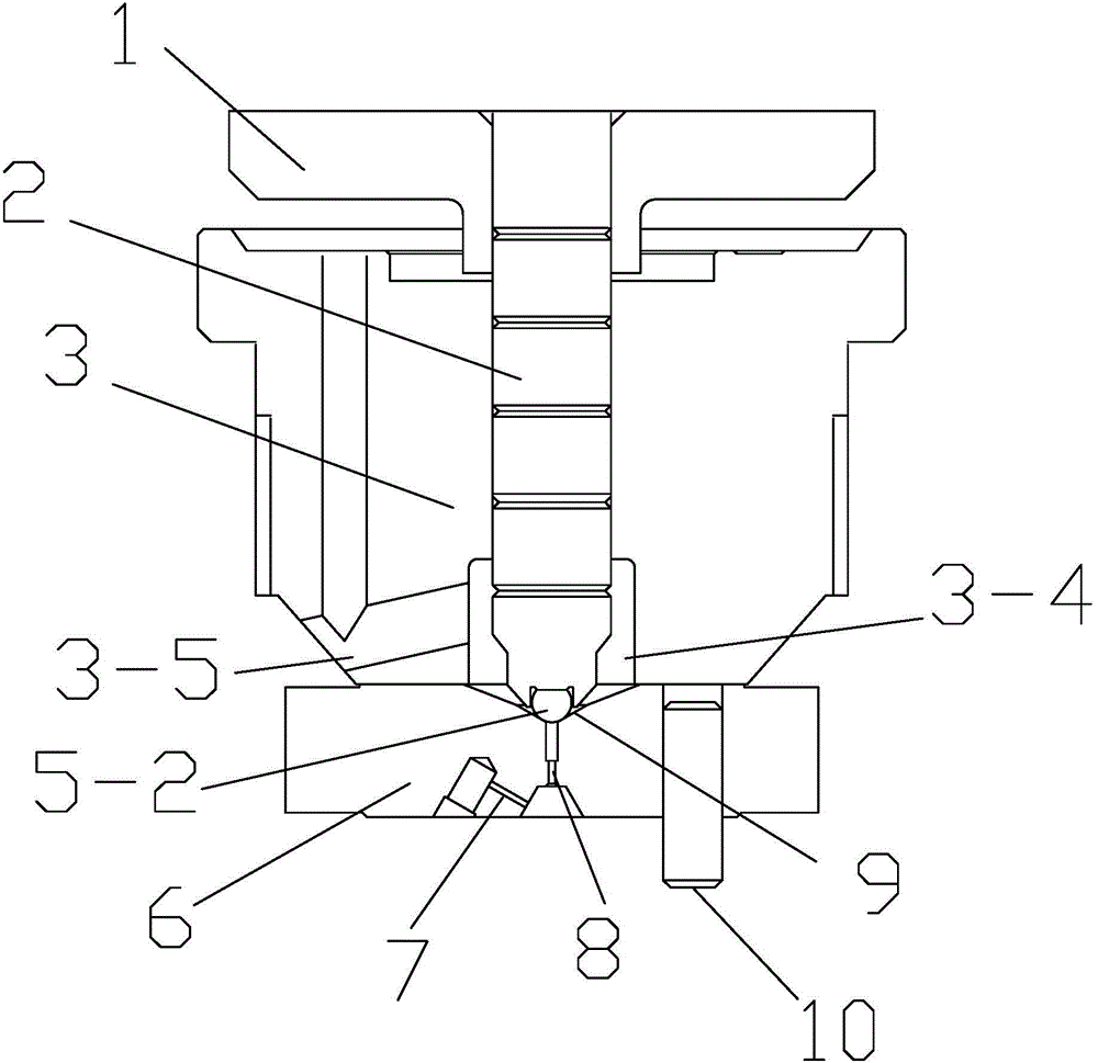
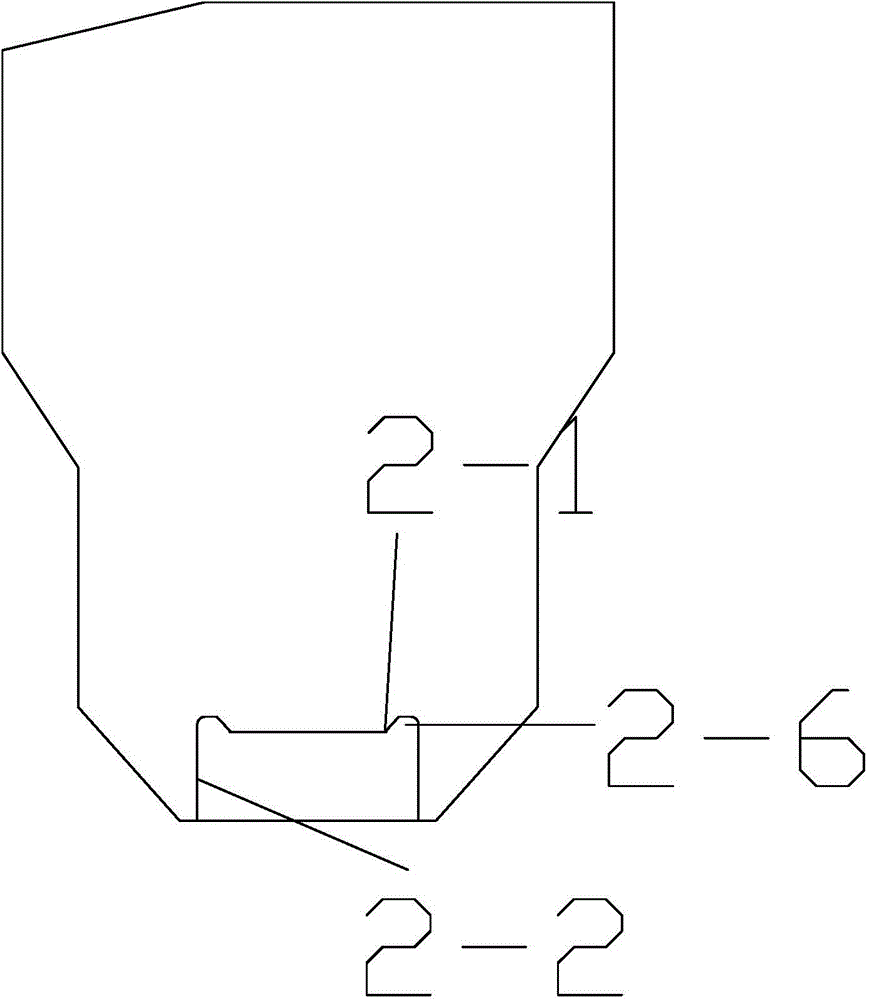
[0035] Such as figure 2 and Figure 4 Shown is a schematic diagram of an embodiment of a high-pressure common rail injector crown ball control valve provided by the present invention, which includes an armature 1, a control rod 2, a valve body 3, a ball seat 4, and a valve seat 6. The armature 1 is set At the upper end of the control rod 2, the valve body 3 is arranged on the valve seat 6, and the control rod 2 extends into the valve body 3 through the guide hole 3-2, and it also includes a crown ball 5-2, which is a belt There is a crown ball with plane B5-1, the crown ball 5-2 is set between the control rod 2 and the oil outlet orifice 8 of the valve seat 6 and the crown ball 5-2 is close to the high-precision conical surface 9 of the valve seat 6, The lower end of the control rod 2 is provided with a groove structure with an opening facing downward. The cross section of the groove structure is circular and the central axis of the groove structure coincides with the centra...
Embodiment 2
[0043] Such as Figure 5 and Figure 6 Shown is a schematic diagram of an embodiment of a high-pressure common rail injector crown ball control valve provided by the present invention, which includes an armature 1, a control rod 2, a valve body 3, a ball seat 4, and a valve seat 6. The armature 1 is set At the upper end of the control rod 2, the valve body 3 is arranged on the valve seat 6, and the control rod 2 extends into the valve body 3 through the guide hole 3-2, and it also includes a crown ball 5-2, which is a belt There is a crown ball with plane B5-1, the crown ball 5-2 is set between the control rod 2 and the oil outlet orifice 8 of the valve seat 6 and the crown ball 5-2 is close to the high-precision conical surface 9 of the valve seat 6, The lower end of the control rod 2 is provided with a groove structure with an opening facing downwards. The cross section of the groove structure is circular and the central axis of the groove structure coincides with the centr...
Embodiment 3
[0048] Such as Figure 7 and Figure 8 Shown is a schematic diagram of an embodiment of a high-pressure common rail injector crown ball control valve provided by the present invention, which includes an armature 1, a control rod 2, a valve body 3, a ball seat 4, and a valve seat 6. The armature 1 is set At the upper end of the control rod 2, the valve body 3 is arranged on the valve seat 6, and the control rod 2 extends into the valve body 3 through the guide hole 3-2, and it also includes a crown ball 5-2, which is a belt There is a crown ball with plane B5-1, the crown ball 5-2 is set between the control rod 2 and the oil outlet orifice 8 of the valve seat 6 and the crown ball 5-2 is close to the high-precision conical surface 9 of the valve seat 6, The lower end of the control rod 2 is provided with a groove structure with an opening facing downward. The cross section of the groove structure is circular and the central axis of the groove structure coincides with the centra...
PUM
 Abstract
Description
Claims
Application Information
 - R&D
- Intellectual Property
- Life Sciences
- Materials
- Tech Scout
- Unparalleled Data Quality
- Higher Quality Content
- 60% Fewer Hallucinations
Browse by: Latest US Patents, China's latest patents, Technical Efficacy Thesaurus, Application Domain, Technology Topic, Popular Technical Reports.
© 2025 PatSnap. All rights reserved.Legal|Privacy policy|Modern Slavery Act Transparency Statement|Sitemap|About US| Contact US: help@patsnap.com


