High pressure common rail injector crown ball control valve

A high-pressure common rail and fuel injector technology, used in machines/engines, fuel injection devices, engine components, etc., can solve the problems of high precision, small concave spherical surface size, unreliable sealing, etc. Low difficulty and the effect of improving high-pressure sealing

Active Publication Date: 2017-05-31
莆田市博泰动力设备有限公司
View PDF6 Cites 0 Cited by
  • Summary
  • Abstract
  • Description
  • Claims
  • Application Information

AI Technical Summary

Problems solved by technology

[0004] The domestically processed ball seat 4 is small in size and high in precision due to the concave spherical surface, and the processing accuracy cannot meet the requirements, and the steel ball 5 is easy to wear. At the same time, because the steel ball 5 rotates, the sealing surface in contact with the tapered surface 9 will change, so that the seal is not stable. Reliable, affects the fuel supply performance of the injector
The price of imported equipment for processing concave spherical surfaces is too high, and it is difficult for ordinary domestic factories to accept

Method used


Image

  • High pressure common rail injector crown ball control valve
  • High pressure common rail injector crown ball control valve
  • High pressure common rail injector crown ball control valve

Examples


Embodiment 1

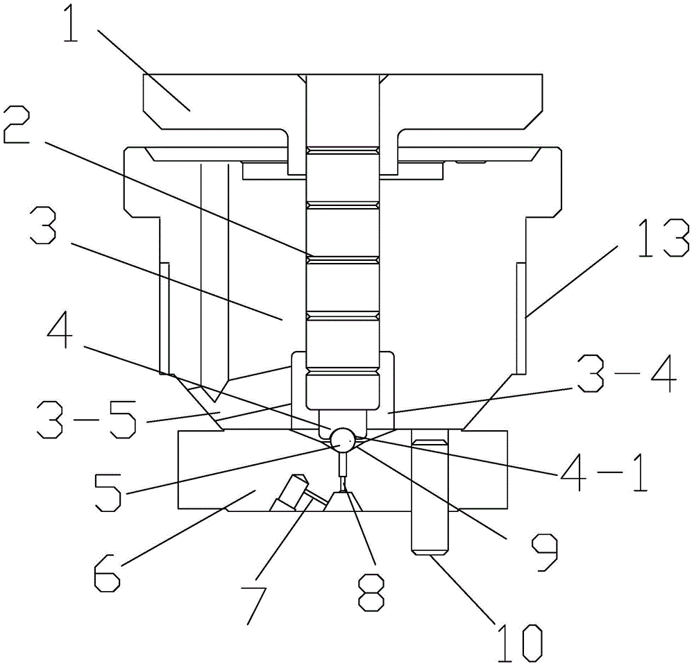
[0035] Such as figure 2 with Figure 4 Shown is a schematic diagram of an embodiment of a high-pressure common rail injector crown ball control valve provided by the present invention, which includes an armature 1, a control rod 2, a valve body 3, a ball seat 4, and a valve seat 6. The armature 1 is set At the upper end of the control rod 2, the valve body 3 is arranged on the valve seat 6, and the control rod 2 extends into the valve body 3 through the guide hole 3-2, and it also includes a crown ball 5-2, which is a belt There is a crown ball with plane B5-1, the crown ball 5-2 is set between the control rod 2 and the oil outlet orifice 8 of the valve seat 6 and the crown ball 5-2 is close to the high-precision conical surface 9 of the valve seat 6, The lower end of the control rod 2 is provided with a groove structure with an opening facing downward. The cross section of the groove structure is circular and the central axis of the groove structure coincides with the centr...

Embodiment 2

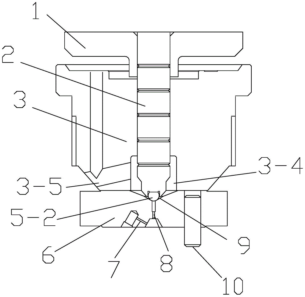
[0043] Such as Figure 5 with Image 6 Shown is a schematic diagram of an embodiment of a high-pressure common rail injector crown ball control valve provided by the present invention, which includes an armature 1, a control rod 2, a valve body 3, a ball seat 4, and a valve seat 6. The armature 1 is set At the upper end of the control rod 2, the valve body 3 is arranged on the valve seat 6, and the control rod 2 extends into the valve body 3 through the guide hole 3-2, and it also includes a crown ball 5-2, which is a belt There is a crown ball with plane B5-1, the crown ball 5-2 is set between the control rod 2 and the oil outlet orifice 8 of the valve seat 6 and the crown ball 5-2 is close to the high-precision conical surface 9 of the valve seat 6, The lower end of the control rod 2 is provided with a groove structure with an opening facing downward. The cross section of the groove structure is circular and the central axis of the groove structure coincides with the centra...

Embodiment 3

[0048] Such as Figure 7 with Figure 8 Shown is a schematic diagram of an embodiment of a high-pressure common rail injector crown ball control valve provided by the present invention, which includes an armature 1, a control rod 2, a valve body 3, a ball seat 4, and a valve seat 6. The armature 1 is set At the upper end of the control rod 2, the valve body 3 is arranged on the valve seat 6, and the control rod 2 extends into the valve body 3 through the guide hole 3-2, and it also includes a crown ball 5-2, which is a belt There is a crown ball with plane B5-1, the crown ball 5-2 is set between the control rod 2 and the oil outlet orifice 8 of the valve seat 6 and the crown ball 5-2 is close to the high-precision conical surface 9 of the valve seat 6, The lower end of the control rod 2 is provided with a groove structure with an opening facing downward. The cross section of the groove structure is circular and the central axis of the groove structure coincides with the centr...


PUM


Abstract

The invention relates to a crown ball control valve of a high-pressure common-rail oil injector. The crown ball control valve comprises an armature, a control rod, a valve body, a ball seat, a valve seat and a crown ball, the armature is arranged at the upper end of the control rod, the valve body is arranged on the valve seat, the control rod penetrates a guide hole to extend into the valve body, the crown ball is a crown ball body with a plane B, the crown ball is arranged between the control rod and an oil outgoing throttling hole of the valve seat and clings to a high-accuracy conical surface of the valve seat, a groove structure with a downward opening is arranged on the lower end portion of the control rod, the bottom surface in an annular groove of the groove structure is a plane A, and the plane B of the crown ball is closely fitted with the plane A. Processing difficulty of the control valve is lowered, and processing accuracy of the control valve is improved. The crown ball control valve has the advantages that the annular groove is designed in the bottom surface of the groove structure, so that convenience is brought to retreating of a processing knife; compared with a concave spherical surface, the plane A in the annular groove of the groove structure is low in processing difficulty and high in processing accuracy.

Description

technical field [0001] The invention belongs to the field of electronically controlled fuel systems, in particular to a crown ball control valve of a high-pressure common rail fuel injector in a diesel engine fuel injection system. Background technique [0002] figure 1 It is an existing high-pressure common rail injector spherical control valve structure (see CN200510086198.0), which consists of an armature 1, a control rod 2, a valve body 3, a ball seat 4, a steel ball 5 and a valve seat 6, and the valve seat 6 The upper processing has an oil inlet orifice 7, an oil outlet orifice 8, a high-precision conical surface 9, and a positioning pin 10. The valve body 3 is provided with an oil storage tank 3-4 and an oil drain hole 3-5. The positioning pin 10 is used for positioning with the fuel injector body, so that the oil inlet orifice 7 is connected with the high-pressure oil passage of the fuel injector body. [0003] Because the control valve controls high-pressure fuel ...

Claims


Application Information

Patent Timeline
Patent Type & Authority Patents(China)
IPC IPC(8): F02M61/04F02M51/06
Inventor 陈忠王九如张伟郭存来黄舒远
Owner 莆田市博泰动力设备有限公司
Why Eureka
Try Eureka