Rotation type air compressor

An air compressor and rotary technology, which is applied to rotary piston machines, rotary piston pumps, rotary piston/swing piston pump components, etc., can solve the problem of large gas impact noise, low work efficiency, and no Output and other issues, to achieve the effect of ensuring the sealing effect, high work efficiency and stable work

Inactive Publication Date: 2014-11-05
王喜来
View PDF10 Cites 2 Cited by
  • Summary
  • Abstract
  • Description
  • Claims
  • Application Information

AI Technical Summary

Problems solved by technology

The cylinder piston has a relatively complex structure, its effective working stroke is relatively short, and its working efficiency is relatively low
During the working process, the piston has to overcome the inertia of the reciprocating cycle, and the direction of the piston's movement changes frequently, so it has a large impact, which will generate a large noise during work, and when the intake valve is used to intake air, it will also produce noise.
[0003] The disclosed air compressor adopts rotary drive, the driving structure of the rotary tongue is complex, the movement reliability is not high, and because the expansion and contraction of the tongue requires a large space, no effective output will be performed during the expansion and contraction of the tongue, and the expansion and contraction Due to the existence of high-pressure gas in the process, there will be a lot of gas impact noise
[0004] From the above analysis, it can be seen that the existing reciprocating piston air compressors and rotary tongue air compressors have disadvantages such as complex structure, low working efficiency, and high working noise.

Method used


Image

  • Rotation type air compressor
  • Rotation type air compressor
  • Rotation type air compressor

Examples


Embodiment Construction

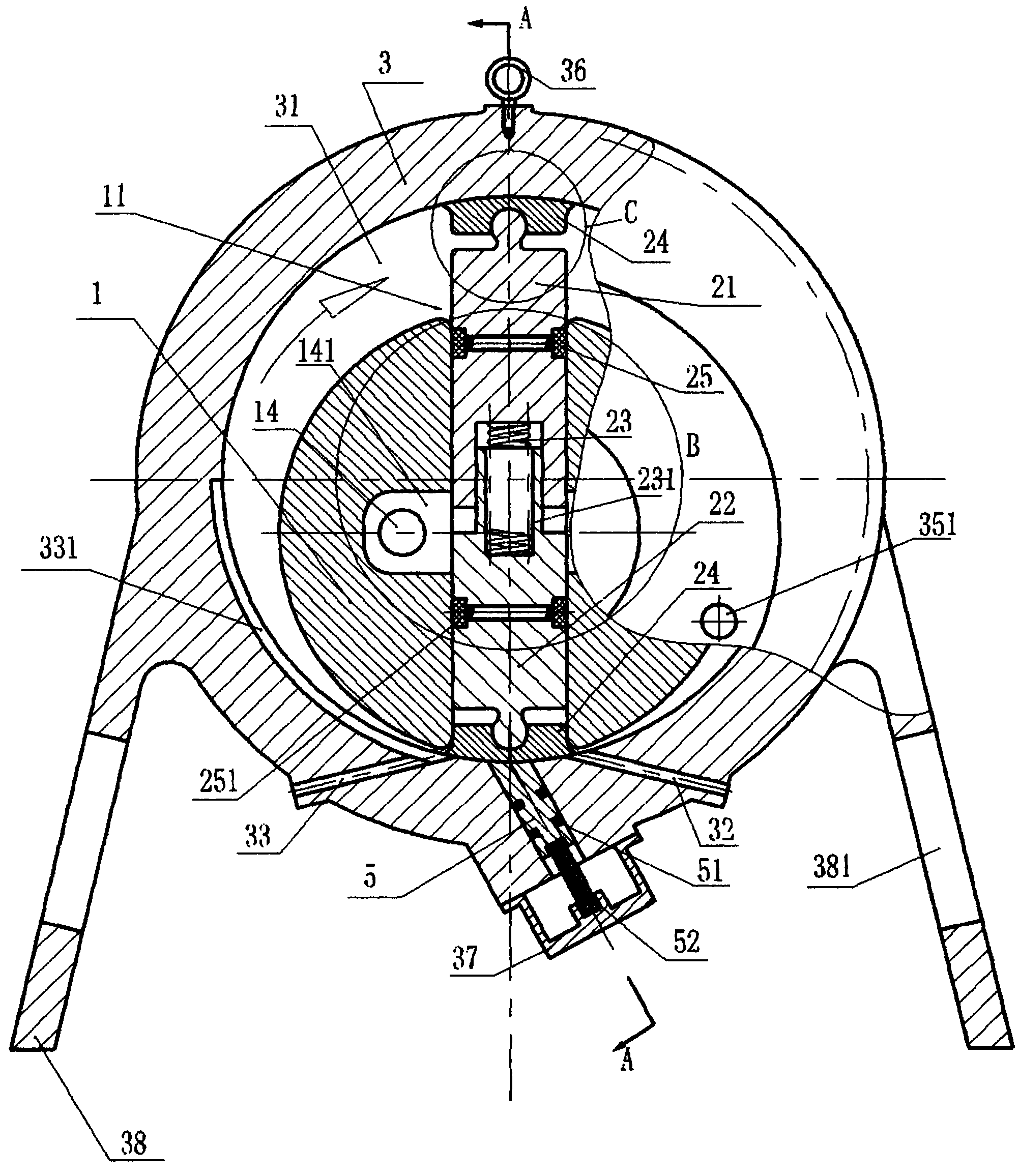
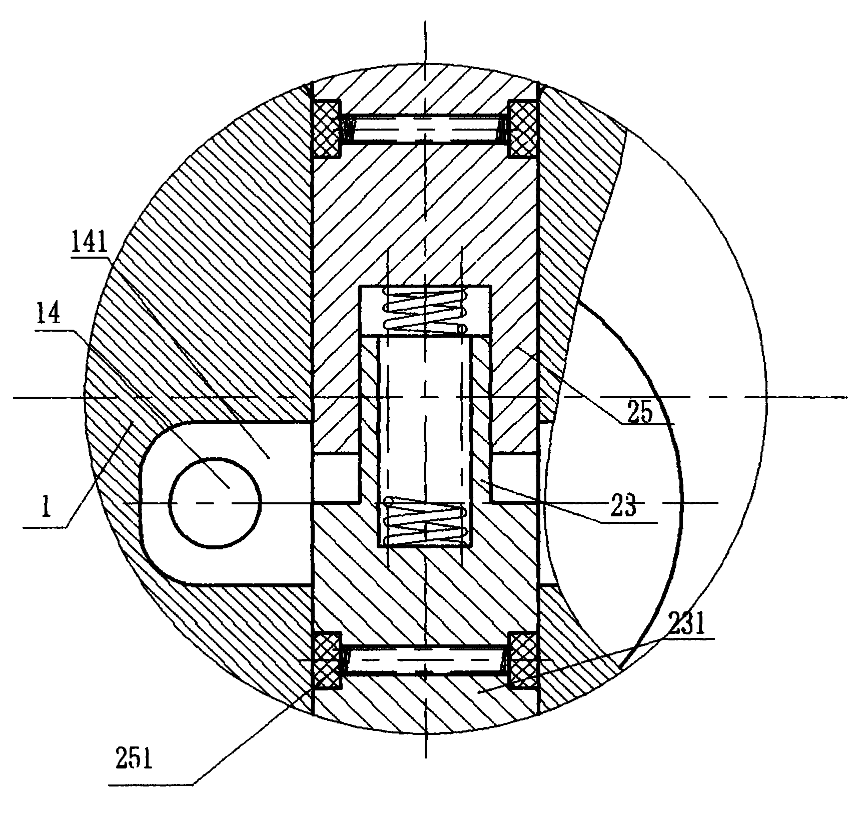
[0037] Such as figure 1 , 2, 8 are diagrams of two different embodiments of the rotary air compressor, the air compressor includes a rotor 1, a housing 3, an air inlet 33, an air outlet 32, and a gap between the rotor 1 and the housing 3 There is a casing cavity 31 that can compress air, and the rotor 1 is eccentrically arranged in the casing cavity 31. There is an airtight contact position between one side of the rotor 1 and the lower side of the casing cavity 31. The air inlet 33 and the air outlet 32 ​​are respectively It is arranged on both sides of the airtight contact part, and the two ends of the housing cavity 31 are provided with end sealing devices; the rotor 1 is provided with a rotor slot 11, and a tongue device 2 that can reciprocate therein is provided in the rotor slot 11, the tongue The end of the tongue of the device 2 is always in airtight contact with the inner wall of the housing cavity 31 of the housing 3 , and can compress the gas in the housing cavity 3...


PUM


Abstract

The invention discloses a rotation type air compressor which comprises a rotor, a shell, an air inlet and an air outlet, wherein a shell chamber which can compress air is formed between the rotor and the shell; the rotor is arranged inside the shell chamber in an eccentric manner; an airtight contact part is arranged between one side of the rotor and the lower side of the shell chamber; the air inlet and the air outlet are respectively formed in two sides of the airtight contact part; end part sealing devices are arranged at two ends of the shell chamber; a rotor groove is formed in the rotor; a tongue piece device which makes reciprocation movement inside the rotor groove is arranged in the rotor groove; the end part of a tongue piece of the tongue piece device is always in airtight contact with the inner wall of the shell chamber of the shell and can compress the air inside the shell chamber when the rotor rotates. When the air compressor operates, as the rotor is arranged in the eccentric manner, one side of the rotor is in airtight contact with the shell chamber, and the tongue piece device makes reciprocation movement inside the rotor groove when the rotor rotates, the air sealed in the shell chamber is compressed, high pressure air is discharged from the air outlet, meanwhile, the air is sucked in through the air inlet, and the purpose of acquiring compressed air is achieved in the circulation and reciprocation movement.

Description

technical field [0001] The invention relates to an air compression device, in particular to an air compressor which rotates and outputs compressed gas. Background technique [0002] Most of the current air compressors are driven by a motor to reciprocate the piston, use the intake valve to inhale air, the piston reciprocates to generate high-pressure gas, and use the exhaust valve to discharge the high-pressure gas. The cylinder piston has a relatively complex structure, its effective working stroke is relatively short, and its working efficiency is relatively low. During the working process, the piston has to overcome the inertia of the reciprocating cycle, and the direction of the piston's movement changes frequently, so it has a large impact, which will generate a large noise during work, and when the intake valve is used to intake air, it will also produce noise. . [0003] The disclosed air compressor adopts rotary drive, the driving structure of the rotary tongue is ...

Claims


Application Information

Patent Timeline
Patent Type & Authority Applications(China)
IPC IPC(8): F04C18/344F04C27/00F04C29/06
Inventor 王喜来
Owner 王喜来
Why Eureka
Try Eureka