Winding worm-gear speed reducer

A technology of worm gear reducer and winding wheel, which is applied in the direction of mechanical equipment, belt/chain/gear, transmission parts, etc., can solve the problems of easy damage of bearings, increase the specification, increase the number of support points, and improve the strength Effect

Inactive Publication Date: 2014-11-05
JIANGSU TAILONG MACHINERY GRP CO CO LTD
View PDF5 Cites 1 Cited by
  • Summary
  • Abstract
  • Description
  • Claims
  • Application Information

AI Technical Summary

Problems solved by technology

[0003] In order to solve the problem that the bearing is easily damaged in the prior art, the object of the present invention is to provide a wound worm reducer

Method used


Image

  • Winding worm-gear speed reducer

Examples


Embodiment Construction

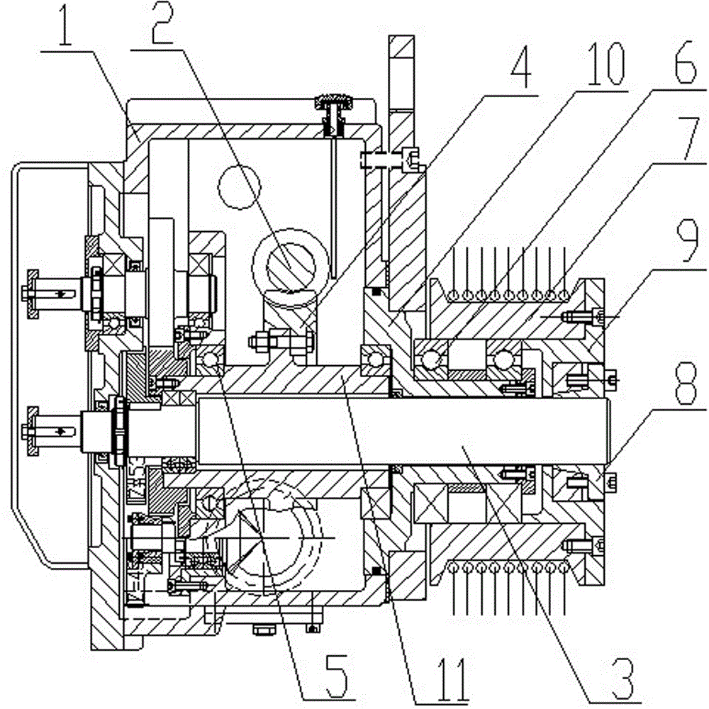
[0012] Below in conjunction with accompanying drawing, the specific embodiment of the present invention is described in further detail:

[0013] As shown in the figure, a winding worm gear reducer includes a casing 1, and a worm 2 and a worm wheel 4 that are engaged with each other are arranged in the casing, and the worm wheel 4 is fixedly connected to the output shaft 3 in series, and the worm wheel 4 A cylinder 11 which is coaxial with the worm wheel and integral with the worm wheel is respectively provided on both ends. The cylinder 11 is supported on the housing 1 through the bearing 5, and the output shaft 3 is sleeved with a sleeve 10 at the protruding end. Two large bearings 6 are sleeved on the sleeve 10, and the outer surface of the large bearings 6 is sleeved with a winding wheel 7, and the shaft end of the output shaft 3 is fixedly connected with an internal expansion wheel 8, and the internal expansion wheel 8 An external expansion wheel 9 is sleeved...


PUM


Abstract

The invention relates to a winding worm-gear speed reducer. A worm and gear mechanism is arranged in a shell body. A worm gear is fixedly connected to an output shaft in series. An extending end of the output shaft is connected with a winding wheel. A shaft sleeve is connected to the extending end of the output shaft in a sleeved mode. The shaft sleeve is fixedly connected with the shell body. A large bearing is connected to the outer surface of the shaft sleeve in a sleeved mode. The winding wheel is connected to the outer surface of the bearing in a sleeved mode. The winding wheel and the extending end of the output shaft are fixedly connected through a connecting device. The worm gear is connected to the output shaft in a sleeved mode. The left end and the right end of the worm gear are provided with circular cylinders connected to the output shaft in a sleeved mode. The circular cylinders are connected with bearings in a sleeved mode and are supported on the shell body through the bearings. The specifications of the bearings are improved, and the intensity of the bearings is improved. At least one bearing group is arranged between the winding wheel and the output shaft. The number of supporting points of the output shaft is increased, the force arm of the output shaft is lowered, force borne by the bearings is lowered, and the risks of bearing damage are reduced.

Description

technical field [0001] The invention relates to a reducer, in particular to a wound worm gear reducer. Background technique [0002] The winding wheel of the winding reducer is often used for cable winding. The existing winding machine usually includes a worm gear mechanism, an output shaft and a winding wheel. Both ends of the output shaft are connected in series to the housing through bearings. It is fixedly installed on the protruding end of the output shaft. Due to the large torque during winding, the bearing at the support of the output shaft bears a large torque, and the bearing is easily damaged. Contents of the invention [0003] In order to solve the problem of easily damaged bearings in the prior art, the purpose of the present invention is to provide a wound worm reducer. [0004] For achieving above object, the technical scheme that the present invention takes is: [0005] A winding worm gear reducer, including a housing, the hous...

Claims


Application Information

Patent Timeline
Patent Type & Authority Applications(China)
IPC IPC(8): F16H37/12F16H57/023
CPCF16H37/12F16H57/023
Inventor 李素珍殷爱国张介禄
Owner JIANGSU TAILONG MACHINERY GRP CO CO LTD
Why Eureka
Try Eureka