Multi-mode stirring friction welding set, system and method

A friction stir and multi-mode technology, applied in welding equipment, manufacturing tools, non-electric welding equipment, etc., can solve problems such as fragile structures, eliminate backlash, improve coaxiality and radial stiffness, and reduce complexity Effect

Pending Publication Date: 2020-11-13
昆山万洲特种焊接有限公司
View PDF0 Cites 1 Cited by
  • Summary
  • Abstract
  • Description
  • Claims
  • Application Information

AI Technical Summary

Problems solved by technology

[0006] Therefore, the technical problem to be solved by the present invention is to overcome the conventional spot welding tools used in the prior art when the functions of seam welding and spot welding are realized, and the structure is easily damaged; Defects of two types of friction stir seam welding, thereby providing a multi-mode friction stir welding welding tool, system and method

Method used


Image

  • Multi-mode stirring friction welding set, system and method
  • Multi-mode stirring friction welding set, system and method
  • Multi-mode stirring friction welding set, system and method

Examples


Embodiment 1

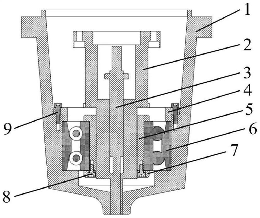
[0088] This embodiment provides a multi-mode friction stir welding welding tool, such as figure 1 As shown, it specifically includes:

[0089] The jacket 1 has an accommodating cavity inside and a through hole at the center of the bottom;

[0090] The sleeve 2 is a hollow tube structure arranged in the accommodation chamber of the jacket 1;

[0091] The stirring needle 3 is arranged in the hollow structure of the sleeve 2 and is coaxial with the sleeve 2;

[0092] The bearing part is set in the accommodating cavity of the jacket 1 and is set outside the sleeve 2;

[0093] The sleeve 2 is sequentially passed through the bearing member and the through hole; the sleeve 2 and the stirring needle 3 can protrude out of the accommodating cavity through the through hole; the sleeve 2 and Stirring pin 3 can be driven by external force to rotate, and can move axially under external force to extend or retract the through hole; there is a first gap between the through hole and the slee...

Embodiment 2

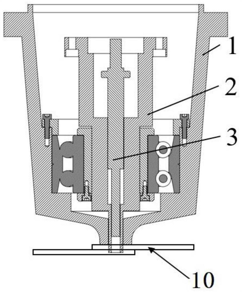
[0104] This embodiment provides a welding method of friction stir spot welding, which uses the multi-mode friction stir welding welding tool described in Embodiment 1. Such as Figure 2a and 2b Two different implementations of friction stir spot welding are shown respectively.

[0105]During welding, the main shaft does not move relative to the workpiece 10 to be welded in a direction parallel to the surface of the workpiece, that is, the horizontal direction is relatively static, and the main shaft moves in a direction perpendicular to the surface of the workpiece, away from the surface of the workpiece to be welded upwards, and close to the surface of the workpiece to be welded for down.

[0106] Such as Figure 2a As shown, it is the spot welding of the cuff 2 under tie mode. The main shaft moves downward to keep the jacket 1 in contact with the upper surface of the workpiece 10 to be welded, and presses the workpiece 10 to be welded; the sleeve 2 penetrates downward in...

Embodiment 3

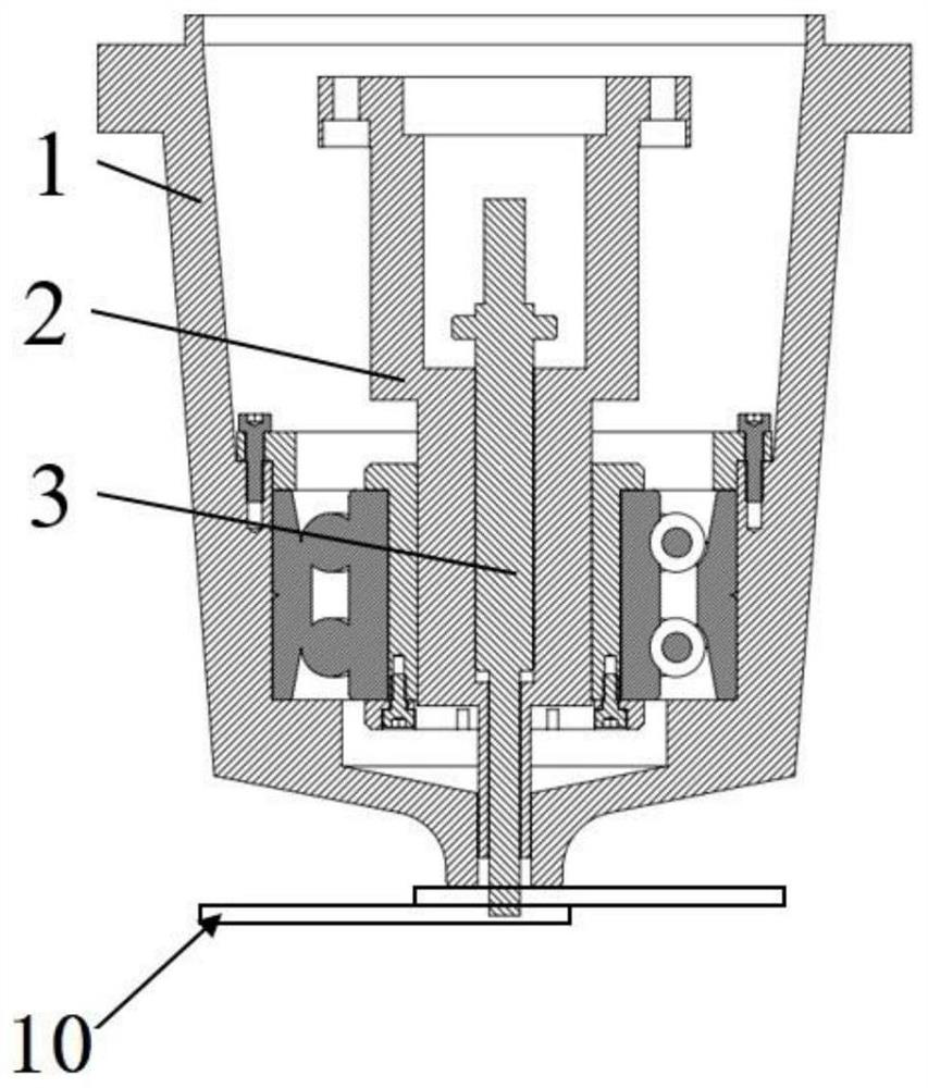
[0110] This embodiment provides a welding method for friction stir seam welding of a movable shoulder, which uses the multi-mode friction stir welding welding tool described in Embodiment 1. image 3 Shows the positional relationship between the sleeve and the stirring pin along the axial direction in the dynamic shoulder welding, Figure 4 It shows the variable welding depth welding mode in the moving shoulder welding.

[0111] Such as image 3 As shown, the lower end surface of the jacket 1 is not in contact with the surface of the workpiece 10 to be welded; the lower end surface of the sleeve 2 is in contact with the surface of the workpiece to be welded to compress the workpiece 10 to be welded; the stirring needle 3 penetrates downward into the workpiece 10 to be welded ; start the main shaft, the main shaft moves relatively in the horizontal direction along the surface of the workpiece 10 to be welded, and the sleeve 2 and the stirring needle 3 rotate in the same direct...


PUM


Abstract

The invention relates to the technical field of stirring friction welding, in particular to a multi-mode stirring friction welding set, system and method. The multi-mode stirring friction welding setcomprises a jacket, a sleeve, a stirring needle and a bearing part, wherein both the sleeve and the stirring needle can rotate under the driving action of external force, and can move along the axialdirection under the driving action of the external force in order to extend out of or retract into a through hole; and the sleeve and the stirring needle can move relatively along the axial direction.The sleeve and the stirring needle are adjusted according to different welding ways in order to adapt to a plurality of different stirring friction welding modes. A bearing part structure is integrated inside the welding set, the coaxiality of the multi-mode welding set is increased, and the moment arms of the sleeve and the stirring needle in the stitch welding process are reduced, so that the bending moments on the sleeve and the stirring needle in the stitch welding process are relatively small, the small deformation and large rigidity of the stirring needle and the sleeve are ensured, thesleeve and the stirring needle can move along the axial direction in the rotating process in order to finish stitch welding, and the durability of the multi-mode stirring friction welding set is realized.

Description

technical field [0001] The invention relates to the technical field of friction stir welding, in particular to a multi-mode friction stir welding welding tool, system and method. Background technique [0002] Friction stir welding is a new type of solid-phase joining technology invented by the British Welding Institute (TWI) in 1991. Its appearance has revolutionized the joining technology of non-ferrous metals such as aluminum alloys, and is known as the most revolutionary Welding method. In just two decades, friction stir welding technology has been successfully applied to the welding of aluminum alloy and copper alloy products in many industrial fields such as aviation, aerospace, ships, trains, weapons, nuclear energy and automobiles. [0003] Friction stir welding, including dynamic shoulder and static shoulder friction stir welding, can only achieve welding with a constant welding depth. For materials with uneven thickness, since the length of the stirring pin is cons...

Claims


Application Information

Patent Timeline
IPC IPC(8): B23K20/12
CPCB23K20/122
Inventor 树西万龙黄体方黄永宪
Owner 昆山万洲特种焊接有限公司
Why Eureka
Try Eureka