Locking mechanism with two-stage unlocking function

A locking mechanism, a two-stage technology, applied to the parts of the connecting device, the coupling device, the two-part connecting device, etc., can solve the problem that the locking mechanism is not applicable, the delay function is not realized, and the locking or unlocking function cannot be realized and other issues to achieve the effect of high practical value

Active Publication Date: 2014-11-05
SICHUAN YONGGUI SCI & TECH CO LTD
View PDF4 Cites 18 Cited by
  • Summary
  • Abstract
  • Description
  • Claims
  • Application Information

AI Technical Summary

Problems solved by technology

[0002] The locking mechanism of the traditional electrical connector can generally achieve the locking or unlocking function through one action. The locking or unlocking is usually achieved by pushing or pulling. The direction of the external force is the same as the direction of movement of the moving end of the connector. In a straight line, this locking method can realize the locking or unlocking function when the operating space is large, but when the operating space is small, especially when the connector is installed in a concave groove-shaped space, the traditional connection The connector locking mechanism will not be able to realize the locking or unlocking function because there is no space for fingers; while new energy vehicles have limited space in the car, and the space for connector installation is even more limited; and new energy vehicles will use large current. Electrical connectors, the size of the electrical connector itself is relatively large. If the traditional locking method is used, it will require a larger installation space to use. It can be seen that the locking mechanism of the traditional electrical connector is not suitable for new energy vehicles. The requirements of high current and small size of the connector; the high current connector used in new energy vehicles requires the connector to have a high voltage interlock function, which requires the locking mechanism of the connector to have a two-stage unlocking function when unlocking, that is, When unlocking, the signal part of the connector is disconnected first, and after a period of time, the power part is disconnected. These two processes need to be delayed, while the traditional locking mechanism completes the unlocking function through one action, and there is no second stage The unlocking function does not implement the delay function. It can be seen that the traditional locking mechanism of the connector is not suitable for the use of new energy vehicles that require the connector to have a two-stage unlocking function.

Method used


Image

  • Locking mechanism with two-stage unlocking function
  • Locking mechanism with two-stage unlocking function
  • Locking mechanism with two-stage unlocking function

Examples


Embodiment Construction

[0021] The present invention will be further elaborated below in conjunction with the accompanying drawings.

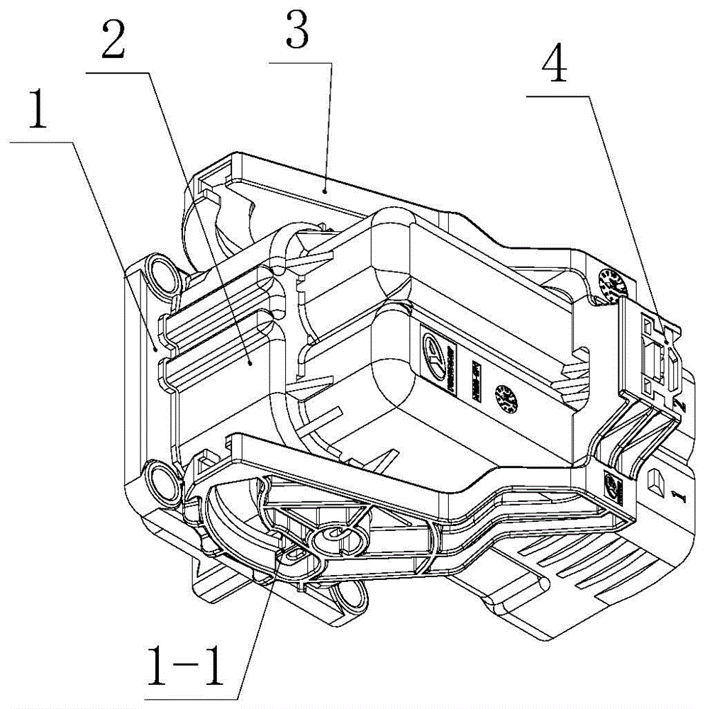
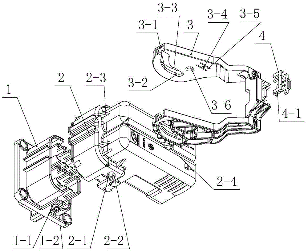
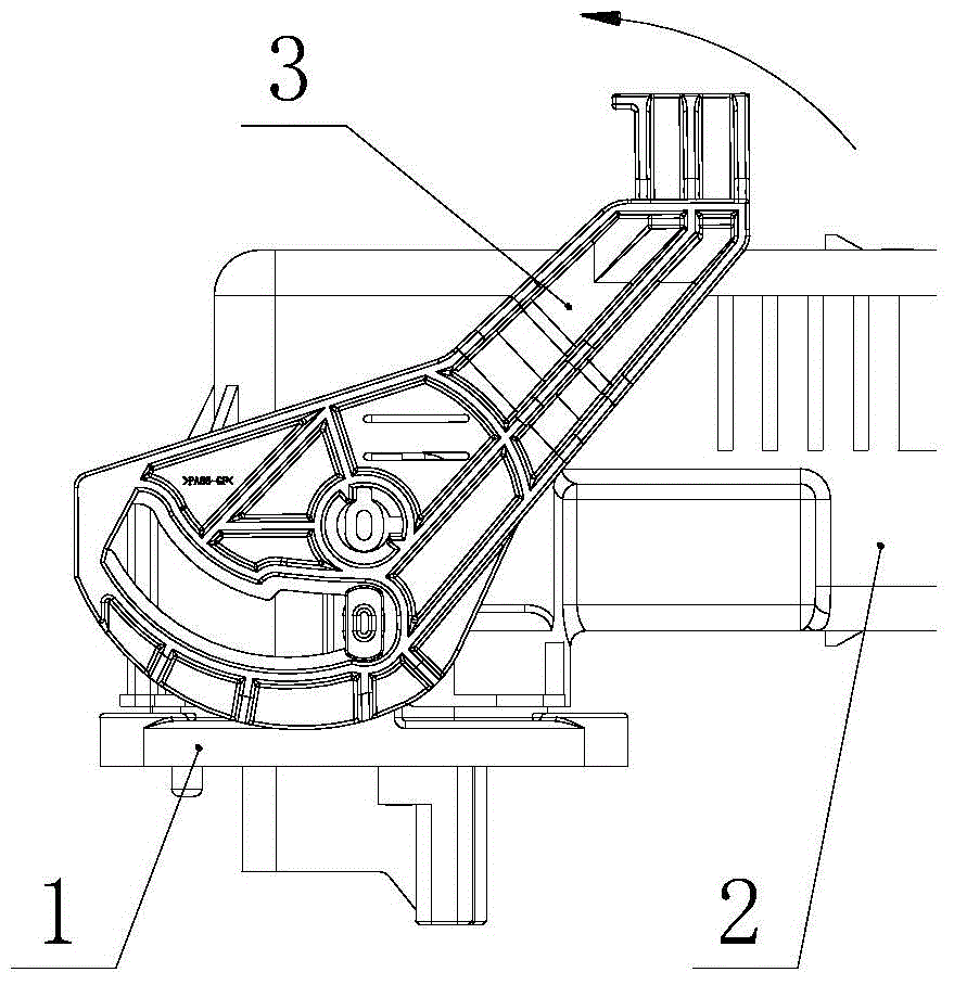
[0022] like Figure 1 to Figure 8 As shown, a locking mechanism with a two-stage unlocking function in an embodiment of the present invention includes a socket housing 1, a plug housing 2, a handle 3 and a lock block 4, and the socket housing 1 and the plug housing 2 are plugged; the lock block 4 is arranged on On the handle 3; both sides of the lock block 4 are provided with a buckle 4-1, the middle of which is provided with a cantilever beam 4-2, and the end of the cantilever beam 4-2 is provided with a half locking block 4-3; the locking block 4 is used in conjunction with the handle 3. A preferred embodiment is that a first rotating shaft 1-1 is provided on both sides of the socket housing 1, and the positions of the two first rotating shafts 1-1 are symmetrical; a flange 1 is provided on the long axis of the first rotating shaft 1-1. -2; a second rotating shaft...


PUM


Abstract

The invention discloses a locking mechanism with the two-stage unlocking function. The locking mechanism comprises a socket shell, a plug shell, a handle and a locking piece. The socket shell and the plug shell are connected in an inserted mode. The locking piece is arranged on the handle. The two sides of the socket shell are respectively provided with one first rotating shaft. The two rotating shafts are symmetrical in position. Each first rotating shaft is provided with a flange in the long axis direction. The two sides of the plug shell are respectively provided with a second rotating shaft. The two second rotating shafts are symmetrical in position. Each second rotating shaft is provided with a protruding key in the long axis direction. The two sides of the handle are symmetrically provided with a locking track and an unlocking track. The unlocking track is divided into a first-stage track and a second-stage track. The locking mechanism is small in size, so that a connector is locked or unlocked in a small space; the locking mechanism has the two-stage unlocking function, the high-voltage interlocking function of the connector can be well achieved, the secondary locking function enables the connector to be locked reliably, and the locking mechanism particularly meets the requirement for the electric connector from a new-energy automobile and has high practical value.

Description

technical field [0001] The invention relates to the technical field of electrical connectors, and relates to a locking mechanism for electrical connectors, which is suitable for the locking mechanism of connectors for new energy vehicles, industrial equipment, and urban rails, and is especially suitable for high-current electrical connectors for new energy vehicles. A locking mechanism that requires two-stage step-by-step unlocking. Background technique [0002] The locking mechanism of the traditional electrical connector can generally achieve the locking or unlocking function through one action. The locking or unlocking is usually achieved by pushing or pulling. The direction of the external force is the same as the direction of movement of the moving end of the connector. In a straight line, this locking method can realize the locking or unlocking function when the operating space is large, but when the operating space is small, especially when the connector is installed ...

Claims


Application Information

Patent Timeline
Patent Type & Authority Applications(China)
IPC IPC(8): H01R13/639H01R24/00
Inventor 李统刚
Owner SICHUAN YONGGUI SCI & TECH CO LTD
Why Eureka
Try Eureka