A continuous and rapid drying device for grain

A rapid drying and grain technology, applied in the direction of preservation of seeds by drying, can solve the problems of being piled up in the bottom of the box that cannot be contacted with hot air, unable to meet large-scale grain production, affecting the rapid drying of grain particles, etc., and achieves ingenious design. , high degree of automation, reasonable structure effect

Inactive Publication Date: 2015-08-26
湖南味百信粮油有限公司
View PDF10 Cites 0 Cited by
  • Summary
  • Abstract
  • Description
  • Claims
  • Application Information

AI Technical Summary

Problems solved by technology

However, the heat source for the drying box with the above structure is only hot air. Considering the accumulation effect of grain particles, only when the grain particles are pushed and turned to the upper surface by the screw push rod, can they have a chance to be in reliable contact with the hot air, and the temperature rises and the humidity is removed. ; more time is piled at the bottom of the box that cannot be in contact with hot air
The removed moisture is mixed with the hot air acting as the heat source, which cannot be separated, and the hot air is used repeatedly, resulting in the saturation of water vapor in the hot air, which in turn affects the rapid drying of grain particles
Therefore, this technical solution cannot meet the needs of large-scale grain production.

Method used


Image

  • A continuous and rapid drying device for grain
  • A continuous and rapid drying device for grain

Examples


Embodiment 1

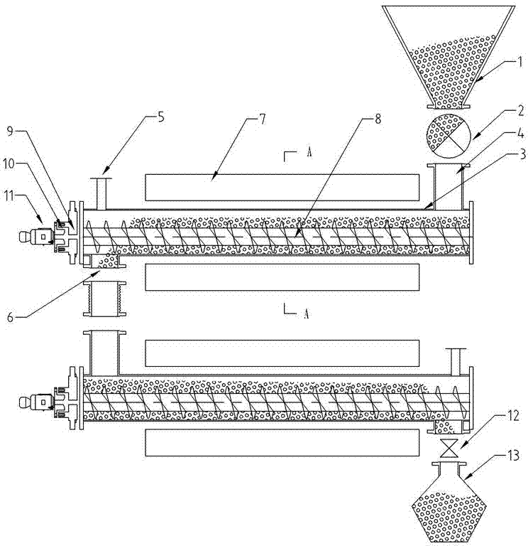
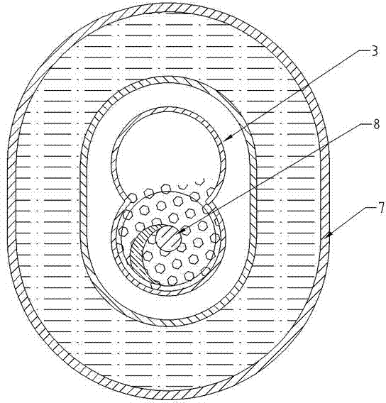
[0017] attached figure 1 And attached figure 2 , a continuous rapid drying device for grain, comprising a feeding system, a heating section and a discharging system connected in sequence; the feeding system is a conical bin 1 with a funnel opening at the bottom and a feeder 2; the feeding system, The heating section and the discharge system are connected through the measurement and control system; the heating section is two or more sections of horizontal pipes arranged from high to low, and the sections are connected in series; the first section of two or more sections of horizontal pipes is In the preheating part, the second or more horizontal tubes are the main heating and drying part; each of the above-mentioned horizontal tubes has basically the same structure, all of which are elongated cylinders 3 with caps on both ends, elongated cylinders 3 It is integrally composed of heat-conducting materials. There is a feed port 4 above one end, a water discharge port 5 connected...

Embodiment 2

[0023] The utility model relates to a continuous and rapid drying device for grain, which comprises a feeding system, a heating section and a discharging system connected in sequence. Structurally, the elongated interlayer heat source box 7 is a boiler steam box; the elongated cylinder body 3 is made of aluminum as a heat-conducting material. All the other are with embodiment 1.


PUM


Abstract

The invention relates to a continuous rapid drying device for grains and belongs to the technical field of drying. The continuous rapid drying device structurally comprises a feed system, a heating section and a discharge system, all of which are orderly connected with each other; the feed system comprises a cone-shaped feed bin and a feeder; the heating section is composed of two or more than two sections of horizontal pipes which are arranged up and down from high to low and connected in series with each other; all the sections of horizontal pipes are basically the same in structure, each section of horizontal pipe is an elongated cylinder of which the two ends are sealed with seal covers, and the part between a feeding hole and a discharge hole of the elongated cylinder is horizontally arranged in the hollow part of an elongated interlayer heat source box; a copper screw rod which is as long as a lower circular-arc-shaped groove is built in the elongated cylinder; the discharge system is composed of a receiving valve and a receiving container. The continuous rapid drying device for grains is used for drying the grain raw materials in such a manner of directly heating by use of a modified screw propeller; the continuous rapid drying device is reasonable in structure, ingenious in design, and also capable of realizing accurate temperature control and thus suitable for drying various grain raw materials relatively high in moisture content.

Description

technical field [0001] The invention relates to a drying technology, in particular to a grain continuous and rapid drying device. Background technique [0002] In the drying process of grains, the traditional method is to use the sun to dry them. The grain dryers widely used in large-scale farms in Mushi generally use elevators to lift the grains, and dry them with hot air through repeated cycles of grains. The disadvantage is that the efficiency is not high. With the large concentration of grain planting area and the wide application of mechanization in harvesting, the traditional method of relying on solar energy to dry grain can no longer adapt to the current wet grain treatment, and grain dryers should also be used. And born. On May 22, 2013, China's utility model authorization announcement number CN 202941340U disclosed a double-layer grain dryer capable of returning air, including a drying box and a hot air blower. The plate divides the inner cavity of the drying box...

Claims


Application Information

Patent Timeline
Patent Type & Authority Patents(China)
IPC IPC(8): A23B9/08
Inventor 曹治
Owner 湖南味百信粮油有限公司
Why Eureka
Try Eureka