Foil plate miniature composite component micro punching forming and connecting device and Foil plate miniature composite component micro punching forming and connecting method

A technology of composite components and connection devices, which is applied in the field of micro-stamping forming-connection devices of foil plate micro-composite components, can solve the problems of low work efficiency and poor precision, and achieve the goal of improving production efficiency, surface flatness and positioning accuracy Effect

Active Publication Date: 2014-11-12
HARBIN INST OF TECH
View PDF6 Cites 5 Cited by
  • Summary
  • Abstract
  • Description
  • Claims
  • Application Information

AI Technical Summary

Problems solved by technology

[0004] In order to solve the problem of low work efficiency and poor precision that composite components need to be manually collected and positioned bef

Method used


Image

  • Foil plate miniature composite component micro punching forming and connecting device and Foil plate miniature composite component micro punching forming and connecting method
  • Foil plate miniature composite component micro punching forming and connecting device and Foil plate miniature composite component micro punching forming and connecting method
  • Foil plate miniature composite component micro punching forming and connecting device and Foil plate miniature composite component micro punching forming and connecting method

Examples


specific Embodiment approach 1

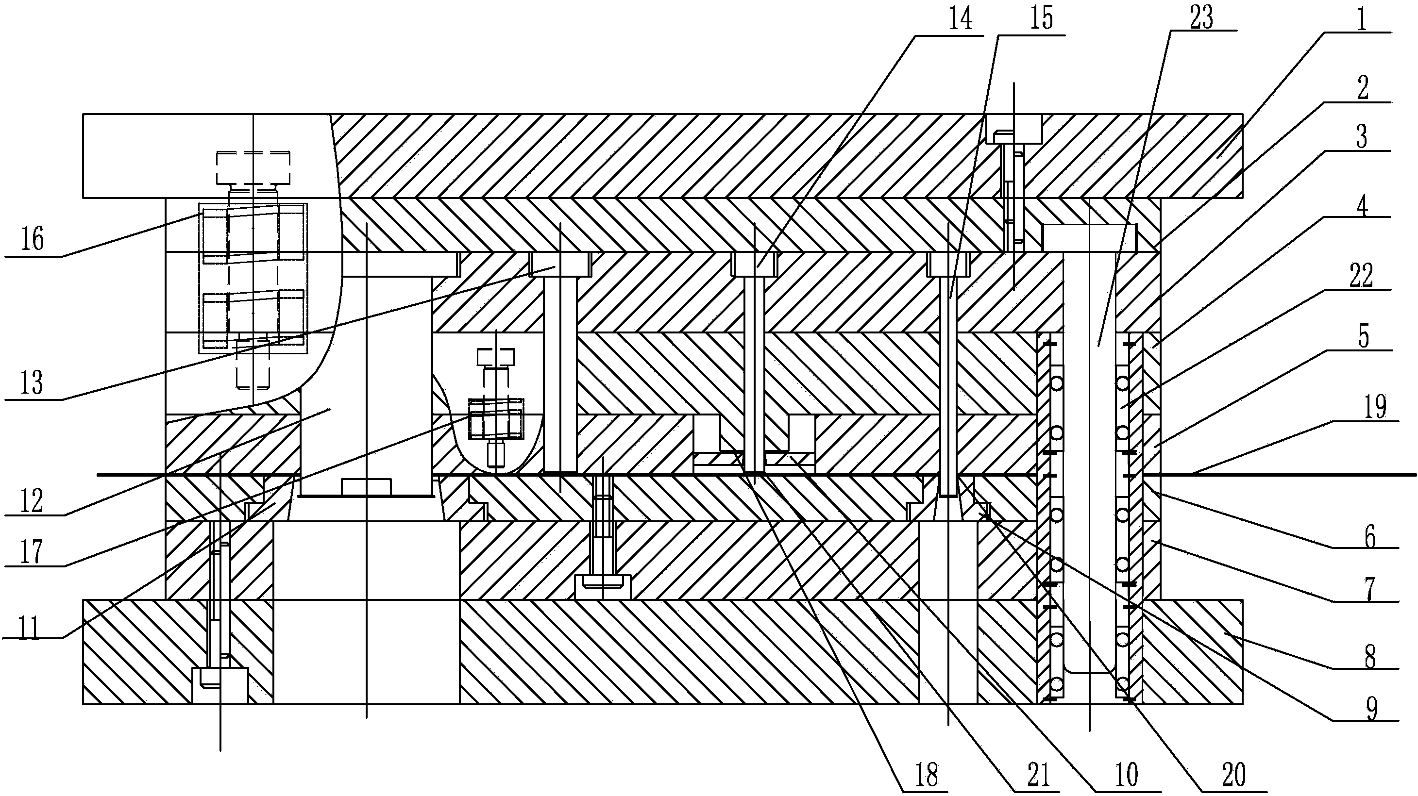
[0022] Specific implementation manner one: such as Figure 1~5 As shown, the foil plate micro-composite member micro-stamping forming-connection device of this embodiment includes an upper template 1, an upper backing plate 2, a convex mold fixing plate 3, a discharge backing plate 4, a discharge plate 5, and a concave mold fixing plate 6. , Lower plate 7, lower template 8, punching die 9, first blanking die 10, second blanking die 11, second blanking punch 12, indenter 13, first blanking punch 14. Blanking punch 15, first spring 16 and second spring 17;

[0023] The die fixing plate 6, the lower backing plate 7 and the lower template 8 are sequentially set up on the lower worktable of the precision stamping machine from top to bottom, the discharge plate 5, the discharge backing plate 4, the convex mold fixing plate 3, the upper cushion The plate 2 and the upper template 1 are arranged on the upper worktable of the precision stamping machine from bottom to top. The blanking die...

specific Embodiment approach 2

[0024] Specific implementation manner two: such as figure 1 As shown, the micro-stamping forming-connecting device of this embodiment further includes a plurality of guide sleeves 22 and a plurality of guide posts 23. The number of guide sleeves 22 and the number of guide posts 23 are set in the same manner, and the upper end of the guide post 23 is installed on the On the backing plate 2, the guide sleeve 22 is sequentially embedded in the discharge backing plate 4, the discharge plate 5, the die fixing plate 6, the lower backing plate 7 and the lower template 8 from top to bottom. Each guide post 23 corresponds to One of the guide sleeves 22 is slidingly fitted with each other. This design can play a role in precise positioning. The other components and connection relationships are the same as in the first embodiment.

specific Embodiment approach 3

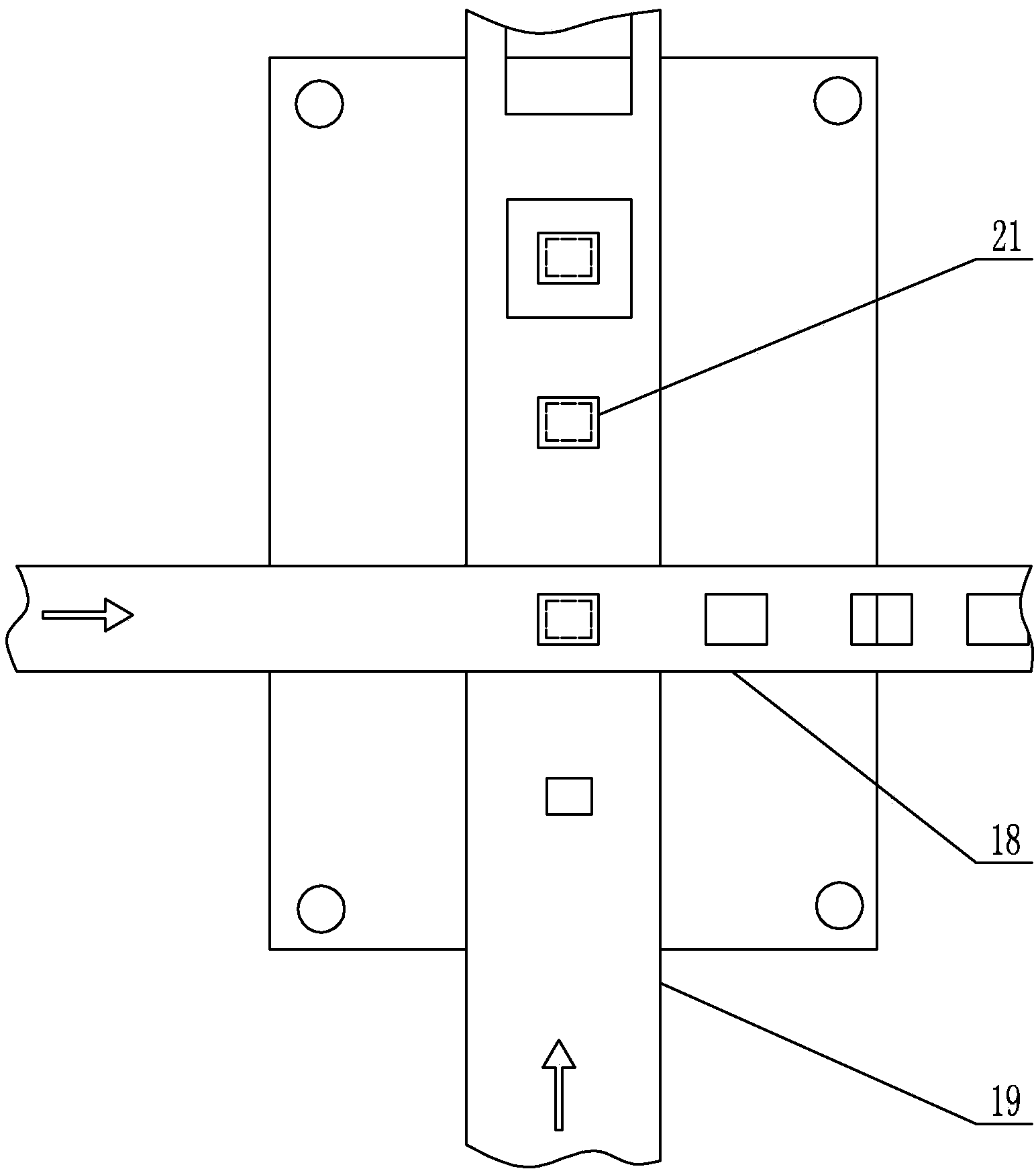
[0025] Specific implementation manner three: such as figure 2 As shown, the number of guide sleeves 22 and the number of guide posts 23 are both three. This design has a good guiding effect, which is beneficial to ensure the forming quality of precision micro-punching and the accuracy of connection positioning. Other components and connection relationships are the same as in the second embodiment.


PUM

PropertyMeasurementUnit
Thicknessaaaaaaaaaa
Thicknessaaaaaaaaaa

Abstract

The invention provides a foil plate miniature composite component micro punching forming and connecting device and a foil plate miniature composite component micro punching forming and connecting method, and relates to a micro punching forming and connecting device and a method. The device and the method provided by the invention aim at solving the problems of low work efficiency and low precision since the composite component connection needs to adopt manual collection and positioning before connection. A first material falling female mold is embedded in a material discharging plate, the upper ends of a second material falling male mold, a press head, a first material falling male mold and a punching male mold are respectively and fixedly arranged on a male mold fixing plate, the lower end of the second material falling male mold sequentially passes through a material discharging pad plate and the material discharging plate to be in vertically aligned arrangement with the second material falling female mold, the first material falling male mold passes through the material discharging pad plate to be in vertically aligned arrangement with the first material falling female mold, the punching male mold passes through the material discharging pad plate and the discharging plate to be in vertically aligned arrangement with the punching female mold, an upper template downwards moves, and titanium, titanium alloy or stainless steel foil plate elements are obtained through punching forming under the effects of the first material falling male mold and the first material falling female mold. The device and the method provided by the invention are used for the micro punching forming and connection of foil plate miniature composite components.

Description

Technical field [0001] The invention relates to a micro-stamping forming-connection device for a foil plate micro-composite component and a connection method thereof. Background technique [0002] In the microelectronics industry, a large number of thin-plate composite components assembled from thin plates of different materials are required. The plate thickness of this type of component is less than 0.2mm, and the geometric size of one of the components is very small, such as the length and width are less than 1.0mm. The existing micro-composite components adopt micro-punching forming, manual collection, positioning and connection composite technology, Technical bottlenecks such as collection after forming, subsequent secondary clamping and positioning; before the connection of the composite components, manual collection and positioning before the connection are required. The production efficiency is low and the accuracy is poor, and it is difficult to meet the needs of mass pro...

Claims


Application Information

Patent Timeline
IPC IPC(8): B21D37/12B21D53/00
Inventor 王春举郭斌单德彬张曼曼徐杰
Owner HARBIN INST OF TECH
Why Eureka
Try Eureka