Cantilever manipulator structure

A technology of manipulator and cantilever, which is applied in the field of cantilever manipulator structure, can solve the problems that the three-coordinate positioning manipulator cannot meet modern production, cannot operate with manipulator, and cannot perform rotary operation, and achieves the effects of good versatility, guaranteed structural strength, and large working environment

Active Publication Date: 2014-11-12
ALFAR SUZHOU AUTOMATION TECH
View PDF9 Cites 10 Cited by
  • Summary
  • Abstract
  • Description
  • Claims
  • Application Information

AI Technical Summary

Problems solved by technology

[0002] The existing manipulator includes a clamping part. After the clamping part is fastened to the corresponding base, the base is supported on a three-coordinate platform that can perform X, Y, and Z axes. According to the position of the workpiece, the position of the three-coordinate platform is adjusted so that The clamping part clamps the workpiece smoothly. With the continuous development of modernization, the three-coordinate positioning manipulator can no longer meet the needs of modern production. A four-axis manipulator for grabbing sheet metal parts", discloses the following technology "composed of one-axis parts, two-axis parts, three-axis parts, four-axis p

Method used


Image

  • Cantilever manipulator structure
  • Cantilever manipulator structure
  • Cantilever manipulator structure

Examples


Example Embodiment

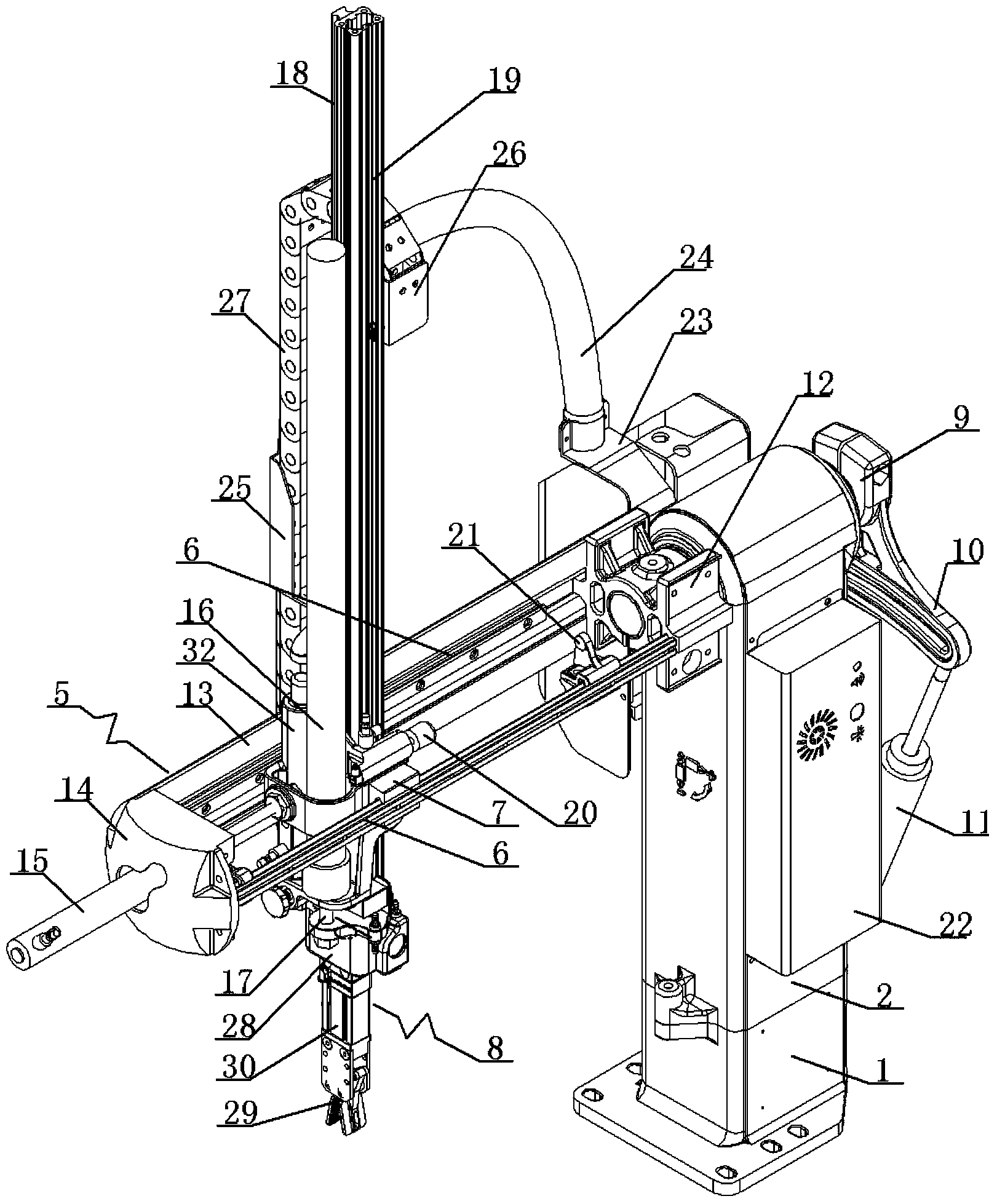
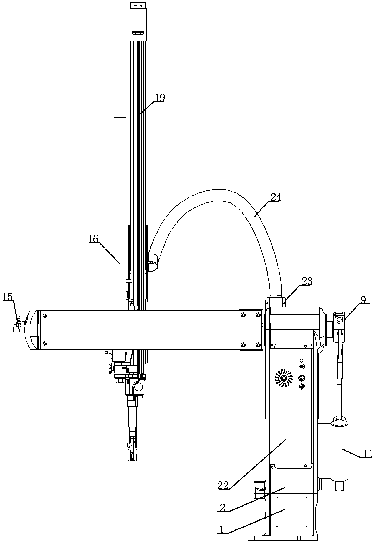
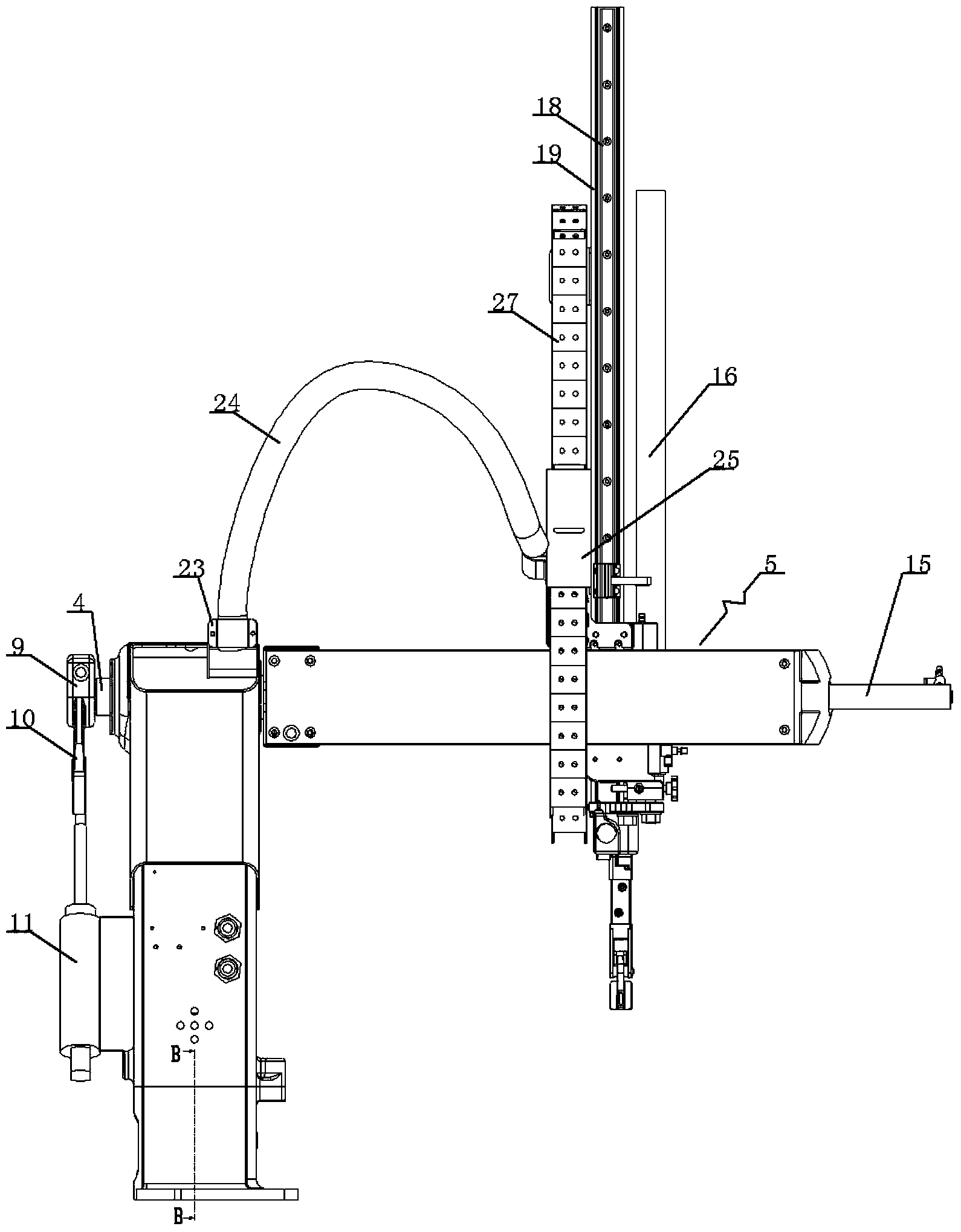
[0025] A cantilever manipulator structure, see Figure 1~Figure 9 : It includes a base 1 and a support 2. The support 2 is supported on the base 1. A bottom rotating shaft 3 is arranged between the center of the bottom of the support 2 and the base. The support 2 can rotate relative to the base 1. The upper part of the support 2 is provided with a horizontal rotating shaft 4 that penetrates the front and rear ends. The horizontal rotating shaft 4 is rotatable. The horizontal rotating shaft 4 is arranged perpendicular to the bottom rotating shaft 3. The front end of the horizontal rotating shaft 4 is provided with a drawing structure 5. The structure 5 is provided with a drawing guide 6 parallel to the horizontal axis of rotation. The upper and lower seats 7 are clamped on the drawing guide 6. The upper and lower seats 7 can move linearly along the drawing guide 6, and the upper and lower seats 7 are fastened with linear drives. The driving direction of the linear driving part i...


PUM


Abstract

The invention discloses a cantilever manipulator structure. Because a rotary frame type structure is adopted for the cantilever manipulator structure, structural strength is effectively guaranteed, the cantilever manipulator structure will not deform when being impacted by all types of tractive force, the cantilever manipulator structure can enter an inclined linear space to carry out operation and can carry out rotary operation in a perpendicular plane, and the cantilever manipulator structure is wide in the application range of working environments and good in universality. The cantilever manipulator structure comprises a base and a support, wherein the support is supported by the base, a bottom rotary shaft is arranged between the center of the bottom of the support and the base, the support can revolve relative to the base, a horizontal rotary shaft penetrating through the front end and the rear end of the support in the front and back direction is arranged on the upper portion of the support, the horizontal rotary shaft can revolve, the horizontal rotary shaft is arranged perpendicular to the bottom rotary shaft, a drawing structure is arranged at the front end of the horizontal rotary shaft, a drawing guide rail parallel with the horizontal rotary shaft is arranged in the drawing structure, an ascent and descent base is installed on the drawing guide rail in a clamped mode and can make linear movement along the drawing guide rail, and a linear driving component is fastened to the ascent and descent base.

Description

technical field [0001] The invention relates to the technical field of manipulator structures, in particular to a cantilever manipulator structure. Background technique [0002] The existing manipulator includes a clamping part. After the clamping part is fastened to the corresponding base, the base is supported on a three-coordinate platform that can perform X, Y, and Z axes. According to the position of the workpiece, the position of the three-coordinate platform is adjusted so that The clamping part clamps the workpiece smoothly. With the continuous development of modernization, the three-coordinate positioning manipulator can no longer meet the needs of modern production. A four-axis manipulator for grabbing sheet metal parts", discloses the following technology "composed of one-axis parts, two-axis parts, three-axis parts, four-axis parts and electric control cabinets, one of which realizes the mechanical arm The lifting movement, the two-axis parts realize the rotary ...

Claims


Application Information

Patent Timeline
IPC IPC(8): B25J9/08B25J9/14
Inventor 施太郎
Owner ALFAR SUZHOU AUTOMATION TECH
Why Eureka
Try Eureka